background image

20

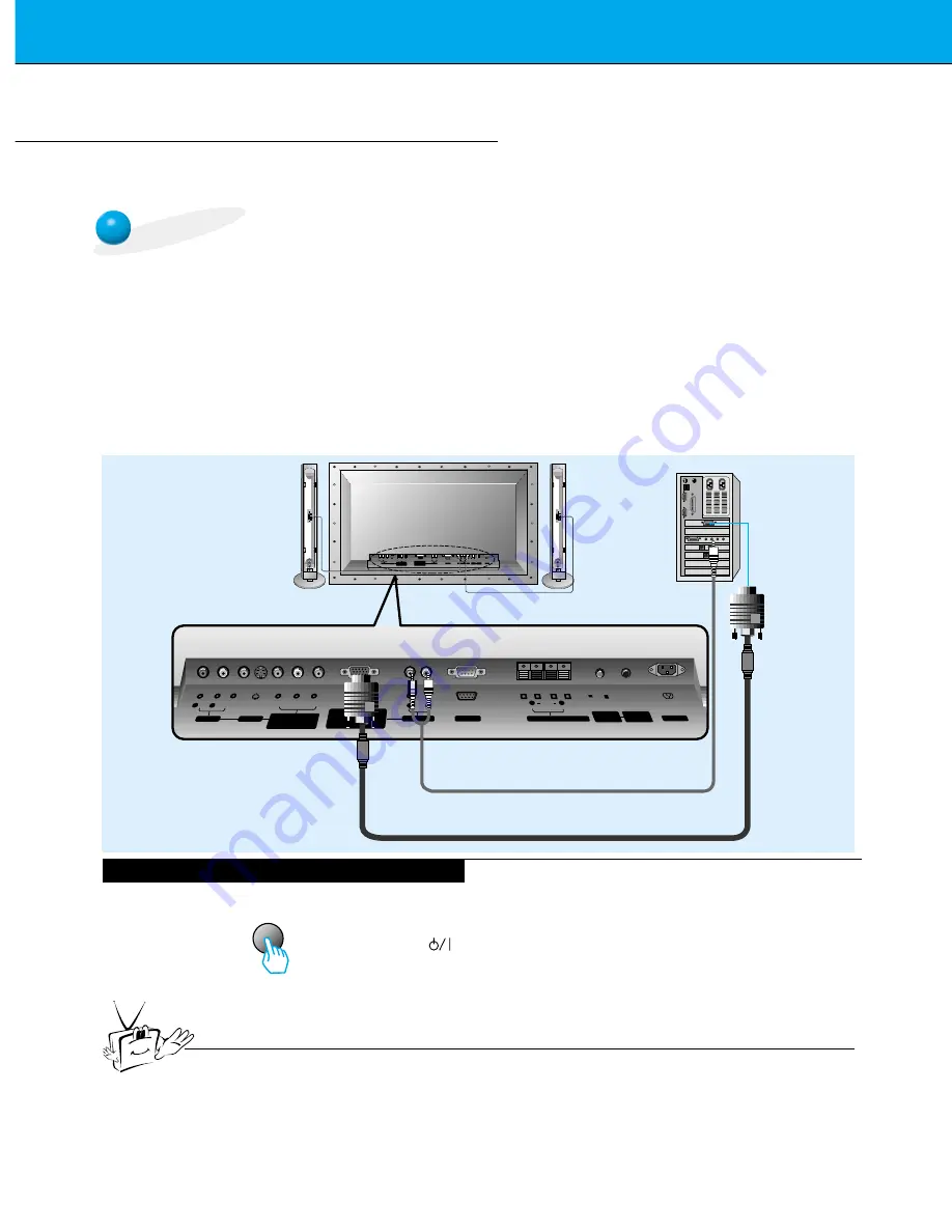
PC Setup

You can easily connect the Plasma Display to your PC for outstanding image and sound.
Use the Monitor to display images and sound from a PC Computer source.

On The Remote Control

Using The Monitor to View Your PC Output

Tips

Setup Instructions: Connecting A PC To Your Monitor

• If the image output of the PC is set higher than

UXGA, no picture will appear on the Monitor.
(UXGA is not supported.)

• Connect the signal cable from the monitor Output

port on the PC to the RGB-PC INPUT
(VGA/SVGA/XGA/SXGA) port on the Monitor.

• Connect the audio cable from the PC to the Audio

ports of the Monitor. (Audio cables are not supplied
with the Monitor.)

• To set up the Monitor to operate within a PC win-

dows environment, select Normal, Standard or

Default monitor.

• The Monitor can not be used for Plug and Play

functionality.

• If your PC computer is equipped with a sound card,

adjust the sound output on the PC.

• It is recommended that the resolution output of the

PC should be set to 1280 x 720 to get the best
quality picture. (Look for a video card that uses the
nVIDIA GeForce 2 pro or similar chipset that 
supports this resolution)

PC Setup

First, turn on the PC computer and press the ON/OFF button on the
Monitor to apply power to it. Second, turn on the display by pressing
the        button on the Monitor or by pressing the POWER button on
the Monitor’s remote control.

Use the 

video/pc

button on the remote control to select the RGB

input source.

Set the resolution output of the PC to SXGA or under (1280 x 1024,
75Hz). (Refer to page 21.)

• Avoid keeping a fixed image on the Monitor's screen for a long period of time. The fixed image may

become permanently imprinted on the screen; use a screen saver when possible.

• If the resolution output of the PC computer is over SVGA, connect the PC to the RGB-PC

(VGA/SVGA/XGA/SXGA) input port on the Monitor. Change the PC computer resolution output
accordingly.

video/pc

(+)

(  )

(+)

(  )

AUDIO

(MONO)

R

L

VIDEO

Y

PB

R

P

AV INPUT

AUDIO

R

L

R

L

EXTERNAL SPEAKER (8

)

AC INPUT

AUDIO INPUT

S-VIDEO

COMPONENT

(480i/480p/720p/1080i)

RGB-PC INPUT

(VGA/SVGA/XGA/SXGA)

RGB-DTV INPUT
(480p/720p/1080i)

(DVD/DTV INPUT)

(+)

(  )

(+)

(  )

AUDIO

(MONO)

R

L

AV INPUT

S-VIDEO

COMPONENT

(480i/480p/720p/1080i)

(DVD/DTV INPUT)

RGB-PC INPUT

R

AUDIO INPUT

EXTERNAL SPEAKER

(8

)

R

L

AC INPUT

L

AUDIO

(VGA/SVGA/XGA/SXGA)

RGB-DTV INPUT
(480p/720p/1080i)

VIDEO

Y

P

B

P

R

RS-232C

RS-232C

CONTROL

LOCK

REMOTE
CONTROL

REMOTE

CONTROL

CONTROL

LOCK

ON/

OFF

ON/

OFF

Monitor Connections Panel

Summary of Contents for P60W26H

Page 1: ...PLASMA DISPLAY PANEL INPUT SELECT VOLUME P60W26P P60W26H OWNER S MANUAL...

Page 2: ...omputer to keep the CPU Central Processing Unit cool the PDP is equipped with cooling fans to cool the Monitor and improve its reliability Therefore a certain level of noise could occur while the fans...

Page 3: ...es Setup and Operation Turning The Monitor On 32 Menu Rotation for Vertical Viewing 33 Checking Features 34 Sleep Timer Setup Setting Sleep Timer Monitor turn off time 35 Picture Sound Auto Picture Co...

Page 4: ...ct all external video and audio equipment see pages 14 20 3 Install batteries in remote control See page 31 4 Turn Monitor on See page 32 5 Turn video source equipment on 6 Select viewing source for M...

Page 5: ...st harmful interference in a residential installation This equipment generates uses and can radiate radio frequency energy and if not installed and used in accordance with the instructions may cause h...

Page 6: ...ion to overturn 9 Attachments Do not use attachments not recommended by the product man ufacturer as they may cause hazards 10 Ventilation Slots and openings in the cabinet are provided for ventilatio...

Page 7: ...amage and will often require extensive work by a qualified technician to restore the product to its normal operation e If the product has been dropped or the cabinet has been damaged f If the product...

Page 8: ...OLUME INPUT SELECT VOLUME Front Panel Controls Main Power Button INPUT SELECT Button Power Standby Indicator Illuminates red in standby mode Illuminates green when the Monitor is turned on Sub Power B...

Page 9: ...RGB PC INPUT R AUDIO INPUT EXTERNAL SPEAKER 8 R L AC INPUT REMOTE CONTROL CONTROL LOCK L AUDIO VGA SVGA XGA SXGA RGB DTV INPUT 480p 720p 1080i VIDEO Y PB PR DVD DTV INPUT 480i 480p 720p 1080i RS 232C...

Page 10: ...p down vol vol enter 0 sleep system off pip input select ratio twin picture freeze easy sound position apc power on button sleep button Refer to p 35 mute button Switches the sound on or off video pc...

Page 11: ...cord power on mute 1 3 2 4 6 5 7 9 8 video pc menu up down vol vol enter 0 sleep system off pip input select ratio twin picture freeze easy sound position apc Remote control Owner s Manual Alkaline ba...

Page 12: ...is designed to be mounted horizontally or vertically Wall Mount Horizontal Installation The monitor can be installed on the wall as shown above For further information refer to the optional Wall Moun...

Page 13: ...nitor vertically the front panel controls must be in the left down side position as shown above For further information refer to the optional Wall Mounting Bracket Installation and Setup Guide Speaker...

Page 14: ...no VCR connect the audio cable from the VCR to the AUDIO L MONO input on the Plasma Monitor If you connect an S VIDEO VCR to the S VIDEO input the picture quality is improved compared to connecting a...

Page 15: ...CR See VCR owner s manual 2 video pc AUDIO MONO R L VIDEO Y PB R P AV INPUT AUDIO R L R L EXTERNAL SPEAKER 8 AC INPUT AUDIO INPUT RS 232C S VIDEO COMPONENT 480i 480p 720p 1080i RGB PC INPUT VGA SVGA X...

Page 16: ...TV service contact your local cable TV service provider s Monitor Connections Panel Cable Converter Box Speakers shown for illustration only video pc TV VCR RF Cable R AUDIO L VIDEO AUDIO MONO R L VID...

Page 17: ...acks on the audio video equipment Video yellow Audio Left white Audio Right red Monitor Connections Panel video pc R L AUDIO VIDEO AUDIO MONO R L VIDEO Y PB R P AV INPUT AUDIO R L R L EXTERNAL SPEAKER...

Page 18: ...Component input jacks on the Monitor Y PB PR Video output jacks on a typical DVD player Y Y Y Y Pb B Y Cb PB Pr R Y Cr PR AUDIO MONO R L VIDEO Y PB R P AV INPUT AUDIO R L R L EXTERNAL SPEAKER 8 AC IN...

Page 19: ...single RGB DTV INPUT for video connections depending on your Set Top Box connectors Then make the corresponding Audio connections See the diagram below for either setup R AUDIO L R AUDIO L Y PB R P DT...

Page 20: ...s resolution PC Setup First turn on the PC computer and press the ON OFF button on the Monitor to apply power to it Second turn on the display by pressing the button on the Monitor or by pressing the...

Page 21: ...03 53 011 100 04 64 062 120 00 35 156 56 25 37 879 60 31 48 077 72 18 46 875 832x624 1024x768 1280x720 1152x864 1152x870 1280x960 1280x1024 75 00 53 674 85 06 56 000 90 00 64 016 100 00 49 725 74 55...

Page 22: ...select a feature you want to use Press the enter button to remove menus Use the up down button to select menus Each press will cycle through the different menus as shown below APC G DRP G CONTRAST 85...

Page 23: ...tton to select AUTO CONFIG and then press the vol G button When AUTO CONFIG has finished OK will be shown on screen If the position of the image is incorrect try Auto adjustment again LANGUAGE G CAPTI...

Page 24: ...ange even though you have adjusted the horizontal or vertical position with this function Press the vol button to adjust until you get desired horizontal or verti cal position and then press the enter...

Page 25: ...o original factory default value To initialize the adjusted value select RESET with the up down button and then press the vol G button Use the up down button to select PHASE and then press the vol G b...

Page 26: ...Twin picture you can watch video cable TV or DVD for sub picture Color of main picture may be different from PIP s in PIP Twin picture mode If input source for main picture is changed while in PIP Twi...

Page 27: ...on in PIP mode Each time you press input select button you toggle between VIDEO S VIDEO and COMPONENT COMPONENT source only works in 480i mode VIDEO S VIDEO COMPONENT PIP INPUT F VIDEO G Moving The PI...

Page 28: ...G DW G PIP G INPUT G SOUND SELECT G POSITION G SOUND M SOUND S OSD ROTATE G ARC G SCREEN G TRANSPARENCY G PIP DW G SET ID G COLOR TEMP G G TO SET PIP DW To select main sound or sub picture inset soun...

Page 29: ...RGB 640x480 only in Vertical frequency 60 Hz With TWIN PICTURE active not all picture formats can be used for the main sub picture Press the twin picture button Each time you press twin picture or vo...

Page 30: ...ce Press the input select button in TWIN PICTURE mode Each time you press the input select button you toggle between VIDEO S VIDEO and COMPONENT COMPONENT source only works in 480i input signal PIP IN...

Page 31: ...rity match with and match with Install two 1 5V AA alkaline batteries Don t mix used batteries with new batteries Notes For Remote Control Operation Make sure these are no objects between the remote c...

Page 32: ...Monitor or press the power on or video pc button on the remote control and then the Monitor will be turned on If the Monitor is turned off with the button on the Monitor Press the main ON OFF button o...

Page 33: ...NORMAL or ROTATE Press the enter button menu up down vol up down vol up down enter Press the MENU button and then use the D E button to select menu Press the G button Select NORMAL if the monitor was...

Page 34: ...u option Press the enter button to remove menu APC G DRP G CONTRAST 100 G BRIGHTNESS 50 G COLOR 50 G TINT 0 G SHARPNESS 50 G MOVE GNEXT AEXIT D E DASP G AVL G TREBLE 50 G BASS 50 G BALANCE 0 G MOVE GN...

Page 35: ...tting press the sleep or vol button repeatedly to select F G SLEEP 1 will be displayed one minute before the Monitor is due to switch off F G F 10 G F 20 G F 30 G F 120 G F 180 G F 240 G F 90 G F 60 G...

Page 36: ...s the screen display as shown below You can also select CLEAR SOFT or USER in the PIC TURE menu USER settings are adjustments made to the picture menu options See next page CLEAR SOFT USER F CLEAR G A...

Page 37: ...uttons to make appropri ate adjustments and then press the enter button Use the up down buttons to select other menu options Adjusting Picture Appearance APC G DRP G CONTRAST 100 G BRIGHTNESS 50 G COL...

Page 38: ...100 G BRIGHTNESS 50 G COLOR 50 G TINT 0 G SHARPNESS 50 G CLEAR SOFT DRP 2 Use the up down button to select CLEAR or SOFT APC G DRP G CONTRAST 100 G BRIGHTNESS 50 G COLOR 50 G TINT 0 G SHARPNESS 50 G C...

Page 39: ...n press the vol G button Adjust BASS and BALANCE in the same way Use the vol buttons to make appropriate adjustment and then press the enter button Use the up down buttons to select other menu options...

Page 40: ...elects the appropriate audio tone levels based on the program content 1 Press the easy sound button 2 Use the easy sound or vol button to select a sound setup Each press of easy sound or vol buttons c...

Page 41: ...nels 3 1 READY Use the up down button to select AVL and then press the vol G button Press the enter button to remove menu DASP G AVL G TREBLE 50 G BASS 50 G BALANCE 0 G ON OFF AVL 2 Use the up down bu...

Page 42: ...ng press the freeze button again Tips If still picture is on the screen for more than 5 minutes the image becomes dark If another function is activated normal screen brightness is restored This is a p...

Page 43: ...press the D E button you toggle between TV and VCR Press the enter button to remove menu OSD ROTATE G ARC G SCREEN G TRANSPARENCY G PIP DW G SET ID G COLOR TEMP G TV VCR SCREEN OSD ROTATE G ARC G SCRE...

Page 44: ...ust menu transparency The TRANSPARENCY adjustment range is 0 5 Press the enter button to remove menu OSD ROTATE G ARC G SCREEN G TRANSPARENCY G PIP DW G SET ID G COLOR TEMP G 5 TRANSPARENCY OSD ROTATE...

Page 45: ...tton The adjustment range of RED GREEN and BLUE is 5 5 Adjust GREEN and BLUE in the same way OSD ROTATE G ARC G SCREEN G TRANSPARENCY G PIP DW G SET ID G COLOR TEMP G G TO SET COLOR TEMP LANGUAGE G CA...

Page 46: ...n aspect ratios A RGB DTV source can only use the 16 9 screen aspect ratio 720p 1080i If 4 3 aspect ratio mode is used for a long time the outline of the image may remain on the screen after you chang...

Page 47: ...supplied with the Monitor The Monitor remote control and front panel controls except main power will not be function al if the Monitor is controlled by a PC computer or other external device How To Co...

Page 48: ...dy 7 RTS Ready to send 8 CTS Clear to send 9 No Connection 1 5 6 9 Pin No 4 and Pin No 6 must be connected on monitor side RS 232C Configurations 2 3 5 4 6 7 8 RXD TXD GND DTR DSR RTS CTS TXD RXD GND...

Page 49: ...ID READY 2 Use the vol button to adjust SET ID to choose the desired monitor ID number and then press the enter button The SET ID adjustment range is 1 99 OSD ROTATE G ARC G SCREEN G TRANSPARENCY G P...

Page 50: ...x0D ASCII code space 0x20 Command Set ID Data Cr OK Acknowledgement The Monitor transmits ACK acknowledgement based on this format when receiving normal data At this time if the data is data read mode...

Page 51: ...t Acknowledgement data feed back presents status about each function Set ID OK x Data x 03 Aspect Ratio Command r G To adjust the screen format You can also adjust the screen format using the ARC Aspe...

Page 52: ...in the Picture menu Transmission Data Min 0 Max 64 Refer to Real data mapping as shown below b Set ID Data Cr Acknowledgement Data Min 0 Max 64 Set ID OK x Data x 09 Color Command c G To adjust the s...

Page 53: ...control PIP DW using the pip twin picture button on remote control or in the Special menu Transmission Data 0 PIP DW off 1 PIP small 2 PIP large 3 Twin picture DW z Set ID Data Cr Acknowledgement Dat...

Page 54: ...djustment turn the Monitor off and then on again 18 Change Into Remote Control Adjustment Mode Command j G To control the Monitor with the remote control while the cable is still connected Transmissio...

Page 55: ...te control Remote Control IR Code NEC Format How To Connect G Output waveform Single pulse modulated with 37 917KHz signal at 455KHz G Configuration of frame G Repeat code G Lead code 1st frame Low cu...

Page 56: ...n R C Button Discrete Power toggle R C Button Power on R C Button System Off R C Button R C Button Discrete Input RGB Power On Discrete Input VIDEO Power On Discrete Input S VIDEO Power On Discrete In...

Page 57: ...ter is off the screen and then let it air dry before you turn on your Monitor Cleaning The Cabinet To remove dirt or dust wipe the cabinet with a soft dry lint free cloth Please be sure not to use a w...

Page 58: ...nd press the VOL UME G button Refer to p 37 Increase the distance between the Monitor and the VCR Activate any function to restore the brightness of the picture If a still picture is on the screen for...

Page 59: ...ight inches mm Depth inches mm Weight pounds kg Power requirement Resolution Color Temperature In operation Humidity In operation P60W26H P60W26P 57 3 1455 34 8 883 3 9 99 154 3 70 AC 120V 60Hz 1280 x...

Page 60: ......

Reviews: