background image

2

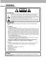
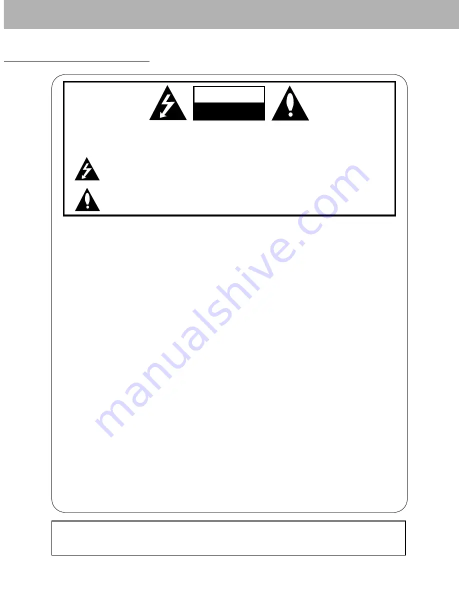
WARNING

WARNING:

TO REDUCE THE RISK OF ELECTRIC SHOCK DO NOT REMOVE COVER (OR BACK). NO
USER SERVICEABLE PARTS INSIDE. REFER TO QUALIFIED SERVICE PERSONNEL.

The lightning flash with arrowhead symbol, within an equilateral triangle, is intended to alert the

user to the presence of uninsulated “dangerous voltage” within the product’s enclosure that may
be of sufficient magnitude to constitute a risk of electric shock to persons.

The exclamation point within an equilateral triangle is intended to alert the user to the presence

of important operating and maintenance (servicing) instructions in the literature accompanying
the appliance.

WARNING:

TO PREVENT FIRE OR SHOCK HAZARDS, DO NOT EXPOSE THIS PRODUCT TO RAIN OR MOIS-
TURE.

FCC NOTICE

• A Class B digital device

This equipment has been tested and found to comply with the limits for a Class B digital device, pursuant
to Part 15 of the FCC Rules. These limits are designed to provide reasonable protection against harmful
interference in a residential installation. This equipment generates, uses and can radiate radio frequency
energy and, if not installed and used in accordance with the instructions, may cause harmful interference to
radio communications. However, there is no guarantee that interference will not occur in a particular instal-
lation. If this equipment does cause harmful interference to radio or television reception, which can be deter-
mined by turning the equipment off and on, the user is encouraged to try to correct the interference by one
or more of the following measures:
- Reorient or relocate the receiving antenna.
- Increase the separation between the equipment and receiver.
- Connect the equipment into an outlet on a circuit different from that to which the receiver is connected.
- Consult the dealer or an experienced radio/TV technician for help.

• Any changes or modifications not expressly approved by the party responsible for

compliance could void the user’s authority to operate the equipment.

CAUTION:

Do not attempt to modify this product in any way without written authorization from Zenith Electronics
Corporation. Unauthorized modification could void the user’s authority to operate this product.

COMPLIANCE:

The responsible party for this product’s compliance is:
Zenith Electronics Corporation
2000 Millbrook Drive
Lincolnshire, Il 60069, USA
Phone: 1-847-941-8000

WARNING

RISK OF ELECTRIC SHOCK
        DO NOT OPEN

WARNING

TO REDUCE THE RISK OF FIRE AND ELECTRIC SHOCK, DO NOT EXPOSE THIS PRODUCT TO
RAIN OR MOISTURE.

Summary of Contents for P42W24B

Page 1: ...Copyright 2002 Zenith Electronics Corporation Installation and Operating Guide Model Numbers P42W24B PLASMA DISPLAY PANEL...

Page 2: ...tions may cause harmful interference to radio communications However there is no guarantee that interference will not occur in a particular instal lation If this equipment does cause harmful interfere...

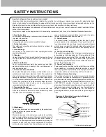
Page 3: ...abinet are provided for ventilation and to ensure reliable operation of the product and to protect it from overheating and these openings must not be blocked or covered The openings should never be bl...

Page 4: ...t only those controls that are covered by the operating instructions as an improper adjust ment of other controls may result in damage and will often require extensive work by a qualified technician t...

Page 5: ...een Adjustments 19 Luminance Noise Reduction 19 Setting Picture Format 20 Split Zoom 20 Picture Size Adjustment 20 PIP Picture in Picture Feature Watching PIP 21 Selecting an Input Signal Source for P...

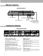
Page 6: ...fer to Speaker Speaker Stand manual 2 RS 232C INPUT CONTROL SERVICE PORT Connect to the RS 232C port on a PC 3 AUDIO INPUT RGB1 INPUT PC DTV INPUT RGB2 INPUT DIGITAL RGB INPUT JACKS Connect the monito...

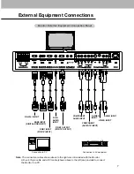
Page 7: ...r External Equipment Connection Panel R L REMOTE CONTROL RGB2 INPUT DIGITAL RGB INPUT RGB1 INPUT PC DTV INPUT RGB1 OUTPUT PC DTV OUTPUT COMPONENT DVD DTV INPUT RS 232C INPUT CONTROL SERVICE EXTERNAL S...

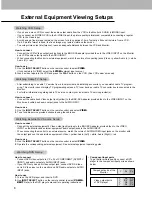
Page 8: ...ght red How to use 1 Use the INPUT SELECT button on the remote control to select VIDEO 2 Operate the corresponding external equipment See external equipment operating guide After subscribing to a cabl...

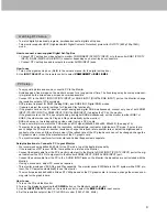
Page 9: ...on video card if using a DVI I cable To see a normal picture match the VGA mode and DVI signal 640x480 848x480 852x480 See page 19 There may be noise associated with the resolution vertical pattern c...

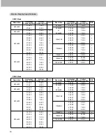
Page 10: ...52x864 1152x870 1280x960 1280x1024 Horizontal Frequency KHz Vertical Frequency Hz RGB2 Mode Monitor Display Specifications Monitor Display Specifications Resolution 640x350 640x400 640x480 800x600 Hor...

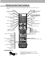
Page 11: ...icture format Refer to p 20 ZOOM Reduces the main picture size Refer to p 20 SPLIT ZOOM Enlarges a screen section Refer to p 20 MENU Displays on screen menus Exits the current menu Memorizes menu chan...

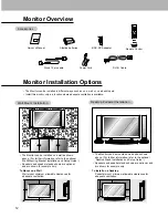
Page 12: ...hes 4 inches 4 inches 4 inches 4 inches 2 inches To Mount on a Wall Wall mount minimum allowable clearances for adequate ventilation To Install on a Desktop Pedestal mount minimum allowable clearances...

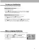
Page 13: ...as turned off with the remote control and the ON OFF button on the Monitor Press the ON OFF button on the Monitor and then press the INPUT SELECT button on the Monitor Or on the remote control press e...

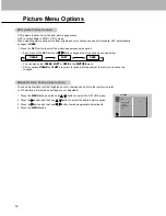
Page 14: ...ture Control User option APC CONTRAST G BRIGHTNESS COLOR SHARPNESS TINT PICTURE 100 1 Press the APC button to select the picture appearance setup option APC Auto Picture Control APC Auto Picture Contr...

Page 15: ...IC are preset for good sound quality at the factory and cannot be changed FLAT SPORTS CINEMA MUSIC USER This function lets you enjoy the best sound without any special adjustment because the Monitor a...

Page 16: ...sible to clear entirely with White Wash 1 Press the MENU button and then use D E button to select the SPECIAL menu 2 Press the G button and then use D E button to select WHITE WASH 3 Press the G butto...

Page 17: ...on and then use D E button to select a color 4 Use the F G button to make appropriate adjustments 5 Press the MENU button The adjustment range of RED GREEN and BLUE is 10 10 Manual Color Manual Color...

Page 18: ...Horizontal Vertical Position ertical Position 1 Press the MENU button and then use D E button to select the SCREEN menu 2 Press the G button and then use D E button to select SCREEN ADJ 3 Press the G...

Page 19: ...video tape Use YNR to reduce the picture noise which may appear on the screen if watching the TV in a weak signal area 1 Press the MENU button and then use D E button to select the SCREEN menu 2 Pres...

Page 20: ...visible 1 Use the ARC button to select the desired picture format Each press of ARC button or F G button changes the picture format as shown below You can also select picture format 16 9 4 3 or ZOOM i...

Page 21: ...tion on the screen in a clockwise direction PIP F G PIP S PIP F G PIP L PIP F G OFF Selecting an Input Signal Source for PIP Selecting an Input Signal Source for PIP Use the PIP INPUT button to select...

Page 22: ...urce for the T Twin Picture win Picture Use the PIP INPUT button to select an input source for the sub picture Each press of PIP INPUT button or F G button changes the menu option In RGB1 PC for main...

Page 23: ...cable D Sub 9 3 2 5 6 4 8 7 PDP D Sub 9 2 3 5 4 6 7 8 RXD TXD GND DTR DSR RTS CTS TXD RXD GND DTR DSR RTS CTS PC 3 Wire Configurations Not standard D Sub 9 3 2 5 4 6 7 8 PDP D Sub 9 External Control D...

Page 24: ...ash j q 0 1 COMMAND 1 COMMAND 2 DATA Hexadecimal The Monitor transmits ACK acknowledgement based on this format when receiving normal data At this time if the data is data read mode it indicates prese...

Page 25: ...owledgement Using the PC input select either 16 9 or 4 3 screen aspect ratio c Set ID OK Data x 04 Screen Mute Command2 d G To select screen mute on off Transmission Data 0 Screen mute off Picture on...

Page 26: ...panel controls on the monitor and remote control When setting this mode only control the monitor with RS 232C Transmission k m Set ID Data Cr Acknowledgement Data 0 Lock off 1 Lock on If you re not u...

Page 27: ...color temperature Transmission Data Min 0 Max 64 Refer to Real data mapping 2 as shown below k Set ID Data Cr Acknowledgement Set ID OK Data x 24 PIP Input Select Command2 y G To select input source...

Page 28: ...gh custom code Data code Data code TC Tf T1 C0 Carrier frequency FCAR 1 TC fOSC 12 Duty ratio T1 TC 1 3 Repeat frame C1 C2 C3 C4 C5 C6 C7 C0 C1 C2 C3 C4 C5 C6 C7 D0 D1 D2 D3 D4 D5 D6 D7 D0 D1 D2 D3 D4...

Page 29: ...AFH 92H R C Button R C Button R C Button R C Button R C Button Power On Off Discrete IR Code Only Power On Discrete IR Code Only Power Off R C Button R C Button R C Button R C Button R C Button R C Bu...

Page 30: ...p 14 Keep a certain distance between the Monitor and the VCR Activate any function to restore the brightness of the picture If still picture is on the screen for more than 5 minutes the screen gets d...

Page 31: ...long time such as a vacation it s a good idea to unplug the power cord to protect against possible damage from lightning or power surges Early malfunctions can be prevented Careful and regular cleani...

Page 32: ...P N 3828VA0361D RF02RA 206 3849...

Reviews: