6
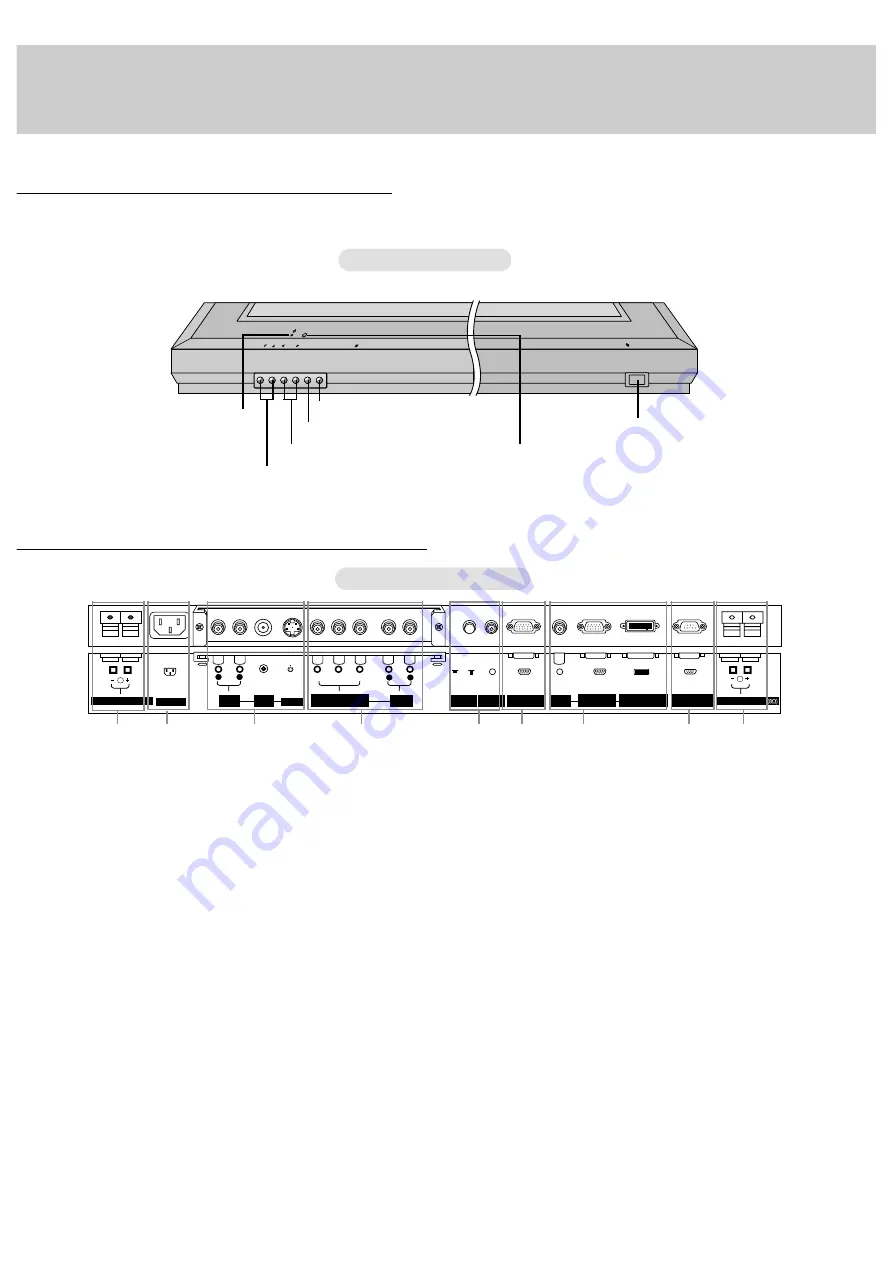
Monitor Controls
Connection Options
VOL.
MENU INPUT SELECT
ON/OFF
Main Power Button
INPUT SELECT Button
VOLUME (
F
,
G
) Buttons
Power Standby Indicator
Illuminates red in standby
mode, Illuminates green when
the Monitor is turned on
Remote Control Sensor
MENU Button
D
,
E
Buttons
Y
P
B
P
R
( )
( )
R
(MONO)
R
AUDIO
ON/
OFF
L
R
AUDIO
L
( )
( )
L
AC INPUT
(8
Ω
)
EXTERNAL SPEAKER
COMPONENT
(DVD/DTV INPUT)
RGB1 OUTPUT
(PC/DTV OUTPUT)
LOCK
REMOTE
CONTROL
CONTROL
RGB1 INPUT
(PC/DTV INPUT)
INPUT
AUDIO
INPUT
AUDIO
INPUT
AUDIO
INPUT
VIDEO
RGB2 INPUT
(DIGITAL RGB INPUT)
RS-232C INPUT
(CONTROL/SERVICE)
S-VIDEO
EXTERNAL SPEAKER
1
2
3
4
7
8
5
6
1
1.
EXTERNAL SPEAKER (8 ohm output)
Connect to optional external speaker(s).
*For further information, refer to ‘Speaker & Speaker Stand’
manual.
2.
POWER CORD SOCKET
This Monitor operates on an AC power. The voltage is indi-
cated on the Specifications page. Never attempt to operate
the Monitor on DC power.
3.
AUDIO/VIDEO INPUT JACKS
Connect audio/video out from external equipment to these
jacks.
S-VIDEO/AUDIO INPUTS (S-VIDEO)
Connect video out from an S-VIDEO VCR to the S-VIDEO
input.
4.
COMPONENT(DVD/DTV INPUT)/AUDIO INPUT JACKS
5.
REMOTE LOCK Switch
REMOTE CONTROL
When “CONTROL LOCK” is set “ON”, Monitor is operated by
the external control device.
6.
RGB1 OUTPUT(PC/DTV OUTPUT) JACKS
You can watch the RGB1 signal on another monitor, connect
RGB1 OUTPUT (PC/DTV OUTPUT) to another monitor’s
PC input port.
7.
AUDIO INPUT/RGB1 INPUT(PC/DTV INPUT)/
RGB2 INPUT(DIGITAL RGB INPUT) JACKS
Connect the monitor output socket of the PC to this socket.
8.
RS-232C INPUT(CONTROL/SERVICE) PORT
Connect to the RS-232C port on a PC.
Front Panel Controls
Back Connection Panel
Summary of Contents for MU-50PZ41V
Page 32: ......


