Zenith IQB42P97G Installation / Operating Manual | Warranty Download Page 26

P A G E   2 6

206-3524-O

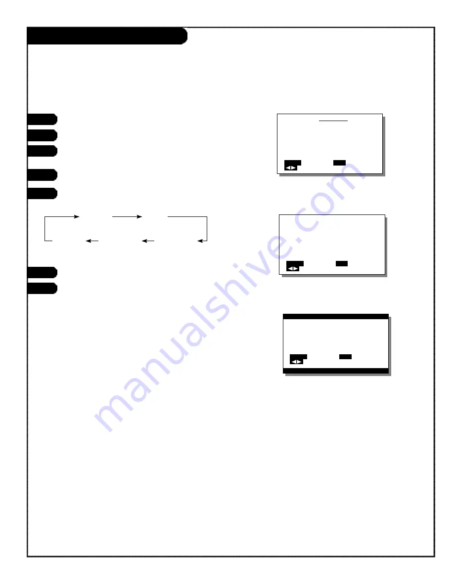
Screen Adjustment (RGB Mode)

RGB MENU

COMMON SETTINGS

PICTURE

POSITION/SIZE

SOURCE
OTHERS

MENU

QUIT

SELECT

SET

ENTER

HEIGHT

           0

MENU

RETURN

ADJUST

SET

NEXT

HEIGHT
                            

–20

MENU

RETURN

ADJUST

SET

NEXT

1

2

Press the MENU button.

Use the ADJUST button to select PICTURE.

Press the SET button to select the CONTRAST
setting.

With the SET button, select CONTRAST.

Use the SET button to moves the selection
to the next item as below.

Adjust levels with the ADJUST button.

Press MENU to return to the Video menu.

VERTICAL       

     HEIGHT 

POSITION  

VERTICAL       HORIZONTAL       HORIZONTAL
LINE

          WIDTH 

            POSITION

3

4

5

6

7

Summary of Contents for IQB42P97G

Page 1: ...machine number IQB42P97G i n s t a l l a t i o n o p e r a t i n g g u i d e w a r r a n t y...

Page 2: ...nd to comply with the limits for a Class A digital device pursuant to Part 15 of the FCC Rules These limits are designed to provide reasonable protection against harmful interference when the equipmen...

Page 3: ...product should follow the manufacturer s instructions and should use a mounting accessory recommended by the manufacturer 8 Transporting Product A product and cart combination should be moved with ca...

Page 4: ...ration e If the product has been dropped or the cabinet has been damaged f If the product exhibits a distinct change in perform ance 19 Replacement Parts When replacement parts are required be sure th...

Page 5: ...wing Wide Screen RGB Mode 16 EZ Functions On Screen Display Settings 17 Internal Speaker Setting 18 Common Settings 19 Adjustments Video Mode Video Adjustments Video Mode 20 Screen Adjustments 21 Inpu...

Page 6: ...INPUT Connects to the S video output terminal of a video deck or video disc play er Component video input ter minal COMPO NENT VIDEO INPUT Connects to the component video output terminal of DVD and s...

Page 7: ...done by your product dealer When installing the display refer to the installation manuals for the options Further be sure that the dis play not does lean to the side or backward Place the power cord...

Page 8: ...g the power cord and contact your product dealer See P44 The plasma display panel has been built using extremely precise and sophisticated technologies More than 99 99 of its pixels are effective Howe...

Page 9: ...over from both sides Then for both left and right sides use screw A 10 mm to attach bracket A to the screw hole highest of the five holes on the side For both left and right sides use screw B 20 mm to...

Page 10: ...the power cord WIDE set Normally used for selecting the desired wide screen POWER Switches the power on or off MODE Selects the input mode MENU For adjusting the video and audio to your taste VOLUME A...

Page 11: ...equipment Connecting to PC To RS 232C terminal Display to analog RGB output terminal To S video output terminal To video output terminal To audio output terminal Cables for connecting external equip...

Page 12: ...deformation Do not wipe the remote controller with volatile liquids such as benzine or paint thinner P A G E 1 2 206 3524 O Remote Button Functions POWER Switches the power on or off MODE Selects the...

Page 13: ...is monitor is designed to operate on standard current 120 volt 60 Hz Ac Do not attempt to operate it on DC current Press the main POWER SWITCH at the rear The power lamp lights red Pressing this switc...

Page 14: ...ith subtitles ZOOM 2 Notes With certain software the monitor may not operate correctly in AUTO mode If so use the WIDE button to switch to the most appropriate screen size WIDE 1 The appropriate wide...

Page 15: ...o display non wide screen conventional normal 4 3 video software over the entire screen the picture will be deformed with part of the edge not visible VIDEO mode is the generic term for VIDEO mode S V...

Page 16: ...n on your remote Press the WIDE button again to select the desired screen size Vertically wide video WIDE 1 2 Notes Use of a wide select function to change the screen size or aspect ratio during comme...

Page 17: ...TINGS Set by pressing the SET button on the remote You will cycle through the available settings to adjust Select Display Press the ADJUST button to adjust the menu item Select either On or Off On The...

Page 18: ...n on you remote On When using the internal speakers regardless of mode RGB When using the internal speakers in RGB mode Video When using the internal speakers in Video mode only S Video When using the...

Page 19: ...NEXT 0 1 3 2 DISPLAY SPEAKER WHITE BALANCE DPMS LANGUAGE 1 2 3 4 5 6 7 8 Adjustment items An adjustment item is selected each time the SET button is pressed DPMS DPMS stands for Display Power Manageme...

Page 20: ...MENU RETURN ADJUST SET NEXT 1 2 Press the MENU button With the ADJUST button select PICTURE Set by pressing the SET button With the SET button select BRIGHTNESS Pressing the SET button moves the sele...

Page 21: ...UIT SELECT SET ENTER VERTICAL POSITION 0 MENU RETURN ADJUST SET NEXT 1 2 Press the MENU button With the ADJUST BUTTON select POSITION SIZE Set by pressing the SET button With the SET button select VER...

Page 22: ...elect Component Video Press the SET button again to select Component Video or Clamp Pulse as below Component Video and Clamp Pulse are set for Component Video mode Video System can be set for Video mo...

Page 23: ...mode In the Clamp Pulse Menu press ADJUST to set Clamp Pulse range AUTO NTSC PAL SECAM 4 43 NTSC M PAL N PAL 3 Video System can be set when the signal is connected to the Video or S Video input termin...

Page 24: ...ET NEXT GAMMA MOTION STILL MENU RETURN SELECT SET NEXT GRADATION MODE 1 MODE 2 MENU RETURN SELECT SET NEXT 1 2 Press the MENU button Use the ADJUST button to select OTHERS Press the SET button to fix...

Page 25: ...GB MENU CONTRAST MENU RETURN ADJUST SET NEXT 1 2 Press the MENU button Use the ADJUST button to select OTHERS Press the SET button to fix the CONTRAST setting With the SET button select GAMMA Use the...

Page 26: ...DJUST SET NEXT 1 2 Press the MENU button Use the ADJUST button to select PICTURE Press the SET button to select the CONTRAST setting With the SET button select CONTRAST Use the SET button to moves the...

Page 27: ...T NEXT MAC MODE MODE 1 MODE 2 MENU RETURN SELECT SET NEXT 1 2 Press the MENU button Use the ADJUST button to select SOURCE Press the SET button to select the MAC MODE With the SET button moves the sel...

Page 28: ...ENU RETURN SELECT SET NEXT 1 2 Press the MENU button Use the ADJUST button to select OTHERS Press the SET button to select GRADATION With the SET button moves the selection to the next item as below S...

Page 29: ...displayed with the setting levels last stored into memory Mode Display Horizontal frequency Vertical frequency Supported signal number dots x lines kHz Hz 1 852 x 480 31 72 59 97 Note When dedicated g...

Page 30: ...5 Component video input Three BNC terminals Y 1Vp p 75 Q Pb B Y 0 7Vp p 75 Q Pr R Y 0 7Vp p 75 Q Compatible format NTSC PAL SECAM N PAL M PAL 4 43NTSC PC RGB input One 15 pin 3 row mD sub terminal Vid...

Page 31: ...you hear is the fan rotating Is the connected tuner being affected by interference from a car train high voltage line neon light or the like Do any of the video settings need readjusting Are the inte...

Page 32: ...DIRECT OR INCIDENTAL DAMAGES OF ANY KIND INCLUDING LOST REVENUES OR PROFITS IN CONNECTION WITH THE PRODUCT SOME STATES DO NOT ALLOW LIMITATIONS ON HOW LONG AN IMPLIED WARRANTY LASTS OR THE EXCLUSION O...

Reviews: