SR25-3828VD0171B
3-2
CL - SERVICING
SERVICE ADJUSTMENTS (continued)
MICROPROCESSOR
Check the following:
IR in on pin 15
+5 volts on pins 27 and 18
Serial Data, Serial Clock on pins 36 and 38
Reset at pin 30
Horiz. SYNC at pin 1, Vertical SYNC at pin 2
R Out at pin 52, G Out at pin 51 and B Out at pin 50
VERTICAL CIRCUIT
Check the following at ICX2100:
Vertical drive at pin 4.
Vertical out at pin 2.
+28 VDC at pin 6.
HORIZONTAL CIRCUIT
Check the following:
Horizontal drive to base of Q3201 predriver.
Driver transformer output at base of QX3203.
Shutdown voltage at RM6009.
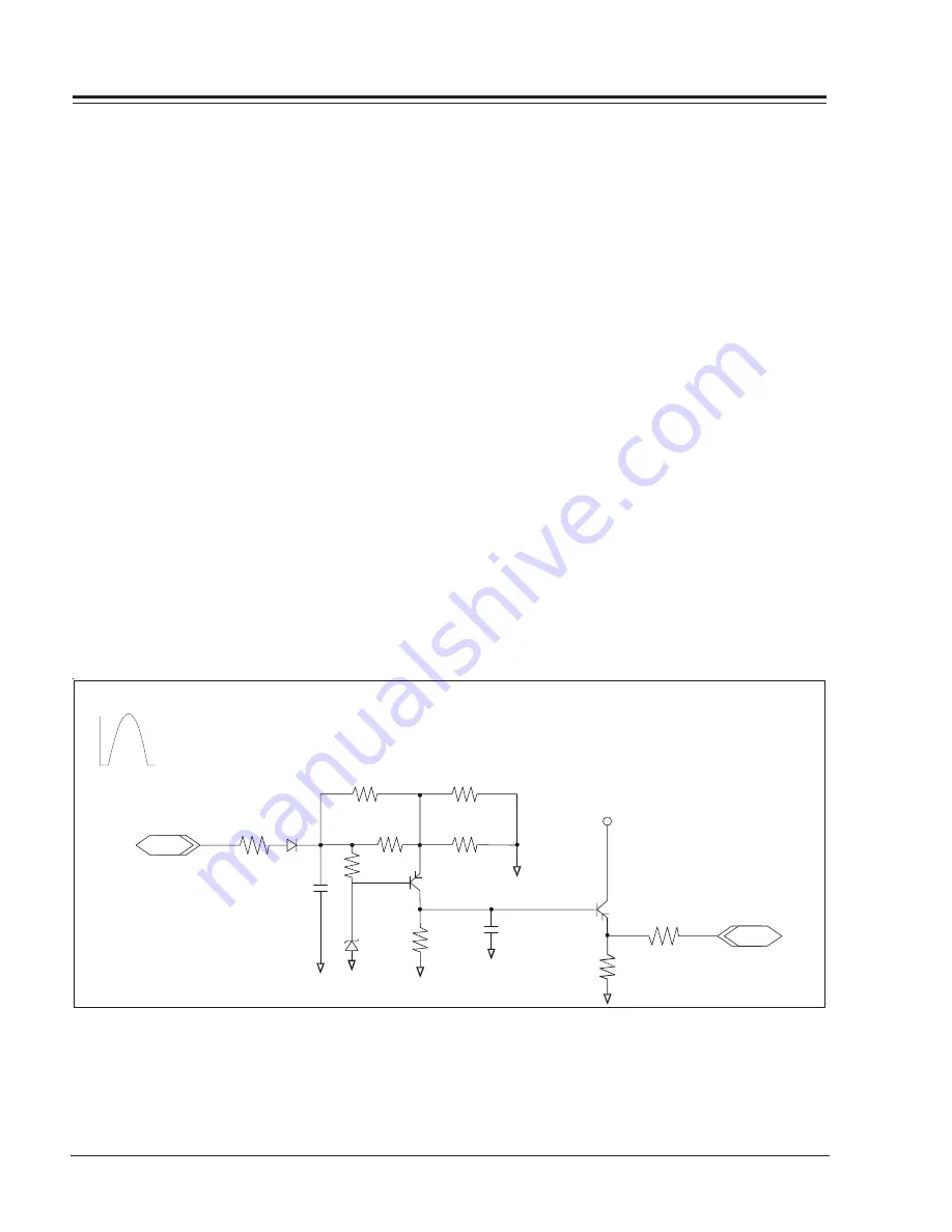
SHUTDOWN CIRCUIT OPERATION
(Refer to figure below)
The flyback pulse voltage from pin 6 of TX3204 (flyback
transformer) is peak detected (rectified) by the action
of the diode DX3006 and capacitor CX3003. This is from
a DC voltage appearing on CX3003 representative of the
CRT anode voltage (HV) produced by TX3204. Precision
resistors RX3013, RX3015, RX3016, and RX3022 divide
this voltage down. This lower voltage appears on the
input (QX3002 collector) of a comparator circuit formed
by RX3008, ZDX3004, QX3002, RMX3009, CX3004,
QX3001, RMX3017 and RMX3021. In the event the CRT
anode voltage becomes excessive, the comparator output
(QX3001 emitter) will go to high level, at approximately
5 volts. This signal (SHUTDOWN) is sent to pin 4 of
IC6000 (microprocessor), and used to turn off the TV
set.
CRT ANODE HIGH VOLTAGE MEASUREMENT PROCEDURE
Each CRT screen size has its own safe operating anode
and shutdown voltage. Critical safety component
(designated with and 'X' in the component designator)
are designed to operate the CRT at a safe operating
anode voltage and provide proper shutdown thresholds.
If replacement of any of these components is deemed
necessary, it is important to use original type Zenith
IN
RX3211
CX3003
DX3006
RX3013
RX3022
RX3015
RX3016
ZDX3004
RX3008
RMX3009
CX3004
RMX3021
SHUTDOWN
TO PIN 4
IC6000
TX3204
From Pin 6
Flyback Pulse
OUT
QX3002
+5v
QX3001
Summary of Contents for H19F34DT Series
Page 62: ...z e n i t h...


