background image

WARNING

Repair work

Repair work can cause serious bodily harm and considerable material
damage.

Only authorized and qualified service personnel is allowed to perform
repair work!

Always comply with the accident prevention regulations!

CAUTION

The local supply voltage must be within the operating voltage range of
the device!

An incorrect operating voltage can cause malfunctions or the risk of fire.

Operate the equipment only with the operating voltages printed on
the housing!

CAUTION

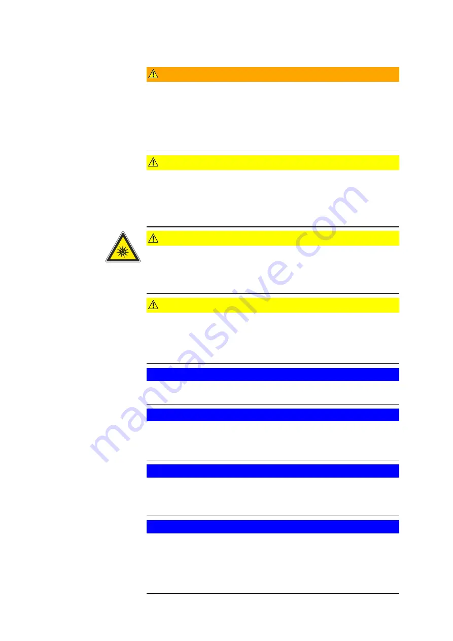
Artificial optical radiation, EN62471 - risk group 2

Directly looking into the light source can be harmful for your eyes.

When you operate the device, do not look into the light source or into
the reflected light for a longer time!

CAUTION

Damaged cables can cause short circuits and the risk of fire.

Replace damaged cables.

Check the cables.

Protect the cables from mechanical load (squeezing, tension, etc.)!

NOTICE

Never connect cables during operation! Never disconnect cables dur‐
ing operation!

NOTICE

When the housing is open, there is risk of electric shock.

Only with the housing closed, the device is ready for operation.

Only open the housing when no voltage is supplied!

NOTICE

Strange objects in the device can jeopardize the operational safety.

Electric shocks and malfunctions can occur.

Do not stick any strange objects into the housing!

NOTICE

Humidity and water can be the cause for malfunctions and damages to
the device.

The devices must not come into contact with water.

Before cleaning, disconnect the power plug!

For cleaning, use a slightly moist cloth!

Important Notes

0000001879_002_EN_30-09-2020

Page 6 (19)

Summary of Contents for Gom T-SCAN hawk

Page 1: ...0000001879_002_EN_30 09 2020 Precise Industrial 3D Metrology Hardware User Manual T SCAN hawk...

Page 2: ...s this manual without warranty of any kind either implied or expressed including but not limited to the implied warranties of mer chantability and fitness for a particular purpose GOM may improve or c...

Page 3: ...5 Information About the Sensor 10 5 1 Sensor Configurations 10 6 Control Elements and LED Indica tors 12 7 Calibrate the Sensor 14 7 1 When is Calibration Necessary 14 7 2 Calibrating Sensor with Cali...

Page 4: ...0000001879_002_EN_30 09 2020 Page 4 19...

Page 5: ...the product or in the vicinity of the prod uct Info The label indicates important application notes and useful information 1 2 Safety and Health Hazard Notes DANGER Danger of explosion due to static e...

Page 6: ...r a longer time CAUTION Damaged cables can cause short circuits and the risk of fire Replace damaged cables Check the cables Protect the cables from mechanical load squeezing tension etc NOTICE Never...

Page 7: ...gy Basic PC knowledge windows based programs and operating systems is expec ted For operating the system optimally the ability to visualize in 3D and a color vision ability are assumed This manual des...

Page 8: ...e the sensor across your measuring object at the proper angle and distance The sensor records the data then an image of the object s surface is generated in the software The built in photogrammetry sy...

Page 9: ...mm 0 035 mm m High precision GOM scale bars With optional internal photogrammetry Laser class IEC EN 60825 1 2M safe for eye exposure Software GOM Inspect Suite GOM Inspect Professional Image and con...

Page 10: ...ggested max part size mm 300 1000 4000 Measuring area in the center of the measuring volume L x W mm 170 x 170 410 x 350 1200 x 900 Average distance between reference points mm 50 120 120 The measurin...

Page 11: ...ing Distance A1 mm Height Measuring Volume B1 mm 0 01 0 1 200 60 0 1 1 320 380 200 130 1 320 560 200 190 Tab 1 T SCAN hawk measuring areas Info The optimal distance for Photogrammetry A3 is always 2 m...

Page 12: ...ators Fig 3 Front and rear control elements Camera A Laser aperture Control button front Camera B Indicator light Control buttons rear Indicator light USB cable power USB cable data connection 0000001...

Page 13: ...measurement Zoom in increase exposure time next step in workflow Change control mode Zoom out reduce exposure time previous step in work flow Start action switch between red blue laser Control Element...

Page 14: ...ations Using the cal ibration object s points in the 2D camera image the software computes the points 3D coordinates It then computes the 3D coordinates back into the 2D camera images This results in...

Page 15: ...and the calibration object The software guides you through the remaining calibration steps In the first step make sure that the calibration object is in the center of the measuring volume The first c...

Page 16: ...icators show the correct position of the sensor Fig 8 Other calibration positions Follow the remaining instructions on the software until the procedure is complete 7 3 Calibration Result At the end of...

Page 17: ...tion object Make sure there are no other highly reflec tive objects near the calibration objects When not calibrating keep the calibration object in the protective sleeve After calibration close the d...

Page 18: ...8 Cabling 8 1 Cabling with Laptop Fig 10 Connecting T SCAN hawk to a laptop 0000001879_002_EN_30 09 2020 Page 18 19...

Page 19: ...9 Declaration of Conformity 9 1 T SCAN hawk Declaration of Conformity 0000001879_002_EN_30 09 2020 Page 19 19...

Reviews: