


14
Cabinet and
riser installation
Riser expansion
Generally, in medium to high-rise
buildings, allowances must be made
for pipe expansion. In applications
supplemented with factory (or field)
supplied between-the-floor riser
extensions, assemble and install
extensions before installing cabinet.
All riser modifications necessitated
by variations in floor-to-floor
dimensions, including cutting off
or extending risers, is the sole
responsibility of the installing
contractor.
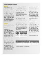
Additional expansion compensation
must be made in the riser system,
in the field, where movement is
expected to exceed the factory
allowances. The “Allowable Riser
Lengths Between System Expansion
Loops” chart on the opposite
page displays the expansion
characteristics of risers compared to
water temperature differential.
Riser connections
Install cabinet with risers as
follows:
■
■
Move cabinet into position.
Caution:
Keep risers off the
floor while moving the cabinet.
■
■
Do not carry units by risers.
■
■
Be sure that all the copper
fittings are clean and free of
dirt. Raise the cabinet upright
and lower it into the riser from
the floor below.
Note:
The top of each riser
is equipped with a 3" deep
swaged connection. There
is sufficient extension at the
bottom to allow insertion of
approximately 2" of the riser
into the swaged top of the riser
below.
■
■
Center risers in the pipe chase
and shim the cabinet level.
Plumb risers in two planes to
assure proper unit operation
and condensate drainage.
■
■
Attach the cabinet assembly
to the floor and the building
structure on at least two sides
using sheet metal angles (field
provided). A field provided
base vibration dampening pad
can be used to help eliminate
transfer of any vibration to
the structure. If vibration
dampening pads are used,
some rough-in dimensional
changes will need to be
considered before installation
due to style and thickness of
the pads. Additional anchorage
can be provided by installing
brackets at the top of the
cabinet (field provided).
■
■
Do not
attach drywall studs to
the equipment cabinet.
■
■
When all units on a riser are
anchored into place, complete
riser joints as follows:
■
■
Verify that all riser joints are
vertically aligned and that
risers penetrate at least 1"
into the swaged joint of the
riser below.
Do not
let riser
joint bottom out.
■
■
Braze riser joints with a
high-temperature alloy
using proper Phos-copper
of Silfos. Soft solder 50-50,
60-40, 85-15, or 95-5 or low
temperature alloys are not
suitable riser weld materials.
■
■
Anchor built-in risers to
the building structure with
at least one contact point.
To accommodate vertical
expansion and contraction
do not
fasten risers rigidly
within the unit.
■
■
Verify that unit shut-off
valves are closed.
Do not
open valves
until the system
has been cleaned and
flushed.
■
■
Flush system, refer to
the System Cleaning and
Flushing Section on page
24 of this manual for more
information.
■
■
Install vents in piping loop,
as required, to bleed the
system of air accumulated
during installation.
Notes
■
■
Riser assemblies are designed to
accommodate a maximum of 1-1/8"
expansion and contraction up to a total
movement of 2-1/4".
■
■
If the total calculated rise expansion exceeds
2-1/4", expansion devices must be used
(field provided).


