17
It is important that the axes of the bore hole is horizontal and in an angle of 90° to the internal wall
surface. If there are bumps in the inner wall or is not vertical then the wall bracket must be aligned
with appropriate means (spacer washer or similar).
Please note that the contact points to the wall are in a vertical level. Based on the design, pay
attention to the availability of sufficient place for the device on the inner wall surface and mark the
bores for fixing the wall bracket.
Leave at least 20 mm of space above so that one can later lift the upper design-cover hood of the
device upwards.
230 VAC network connections are to be prepared on site for the power supply of the device.
This can be done in an in-wall port behind the device.
2.
In case of two-room connection:
In the case of a device with two-room connection, the executions
should also be prepared for air ducts. The side connections can also be alternatively used after
excluding the grid.
3.2.2 Air duct connection (only in the case of two-room connection)
Moving the air ducts and the required accessory (Adapter, curves, sealing tape) should be done before
installing the main device.
When mounting the air ducts, the following points must be taken into account:
•
Assemble the air ducts air-tight to the provided connection stubs. Therefore, use the recommended
sealing tape (accessory article). The sealing tape should be wetted with silicon spray so that the
connection of the air duct is easily done with the casing.
•
Thereby, there is an option to install the air ducts either sideways or behind the device.
•
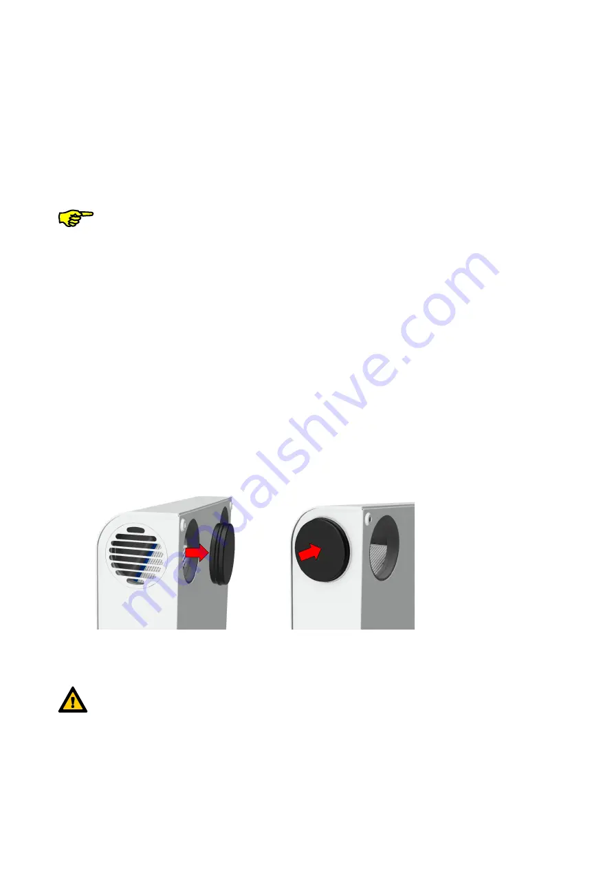
For an assembly behind the device, take the blind plugs from the EPP-Casing and place the air ducts
in the two-room, which is to be ventilated or exhausted. Use the blind plugs, advisable in the delivery
status behind the two-room connections, to seal the side connections.
Two-room connection from behind:
•
Recommendation: Use the „Transition 90/75 on flat 51” (article number 990 322 013) and manage the
channel in the insulation level of the outer wall insulation.
Limitation during the assembly of flat duct flat 51 on the inner wall:
While using the transition piece “Transition 90 on flat 51 / Curve 90°“ (article number 990 322 046), the
connection should lead downward and then towards left or right initially at 90°-angle (“Curve flat 51 H”;
article number 990 322 012).
Summary of Contents for ComfoAir 70
Page 2: ......
Page 32: ...32 3 5 2 Assembly Template measured Figure is not scaled...
Page 43: ......


