3.3 Circuit
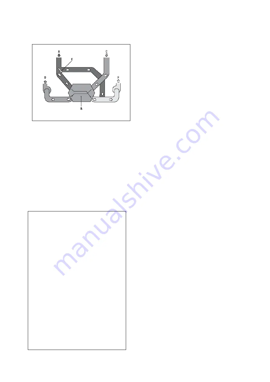
Diagram
Figure 1
The COMFOAIR 140 is equipped with an
anti-freeze system without additional
auxiliary energy. A sensor is installed in
the discharged air duct that, in the event of
the ambient air temperature being too low,
reduces the air intake fan electronically in
1% steps via the internal control system.
Less energy is thus drawn from the
discharged air and freezing of the heat
exchanger is prevented.
Component Overview Figure 1:
#
*Important installation instruction
If a geothermal heat exchanger is not
provided, we recommend the installation
of a preheater unit for the outside air. This
prevents icing of the heat exchanger at
extreme
ambient temperatures.
4. SYSTEM
4.1 Installation
Conditions
The following preconditions must be
satisfied for the proper installation of the
Comfoair 140:
•
The installation location must be
selected such that there is sufficient
space around the unit for the air intake
and outlet connections, the electrical
connections and the waste water
connections, and for maintenance
work.
•
The connecting lines for the air intake
and outlet, the 230 V power supply and
a waste water connection must be
available in the room.
•
In order to prevent condensation, the
outside air and discharged air lines
between unit connection and outside
wall/roof opening must be insulated
vapour diffusion-tight.
•
A double-walled or insulated part must
be used for the roof or outside wall
opening for the discharged air.
•
The Comfoair 140 must be installed in
a frost-free room. The condensate line
must be laid frost-free and with a down
gradient.
•
Extractor hoods may not be connected
to the same system.
In order to ensure
draught-free passage
of air
through your house, air gaps under
or grilles in the doors must be provided.
These must
not be sealed
, as then – just
as with the opening of windows (no or
reduced heat recovery) – the optimum
function of the system cannot be assured.
Windows may be opened during the warm
part of the year.
*
Exhausting of polluted room air, e.g.
from kitchen, bathroom or toilet (A).
The heat exchanger (B) draws heat from
the exhausted air.
Fresh outside air is drawn in (C).
The counterflow heat exchanger (B)
heats the intaken air.
The fresh heated air is delivered i.a. to
the bedroom and living room (D).
The counterflow heat exchanger (B) has
a thermal efficiency of approx. 90%.
Post-heating of the intaken air is
therefore not necessary.
A 100% bypass (E) ensures that the
exhaust air bypasses the heat
exchanger. As a result, the cool outside
air (e.g. from geothermal heat
exchanger) is not heated by the
counterflow heat exchanger. Cool
outside air flows into the house. This
process is controlled automatically
according to the set temperature.


