background image


S

ERVICE  

G

UIDE

Introduction 

 
The scanner, combining with omnidirectional scanning performance and handheld convenience, it is ergonomically 
facilitates scanning of large items that is unable to be presented to any counter-top scanner. It is also equipped with 
single line scanning capability and in stand operation with exclusively designed adjustable stand to benefit for any 
kind of applications required. The scanner has a built-in high speed decoder and instantly decodes any popular 1D 
symbology and optional in decoding of RSS group barcodes. It is also equipped with multi-interface communication, 
which supports RS-232, keyboard and as well as USB interface. 
 
The reading status can be checked with the LED indicator, and buzzer.  The scanner operates with +5VDC from 
Host or external power supply unit. 
 
The scanner includes key features as, 
 

  Button switch in between omnidirectional and single–line scanning capability, ideal for increasing your 

operating efficiency. 

  Powerful 20-line scan pattern yields  


1400 scans per second for omnidirectional scanning 


74 scans per second for single-line scanning 

  Implement with the proprietary real-time hardware decoding technology that ensures instant 

recognition and decoding barcodes 


Ideal for applications at: 

 Retail 

 Point-of-Sale 

 Logistic 

tracking 

 Administration 

 Inventory 

control 

 Manufacturing 


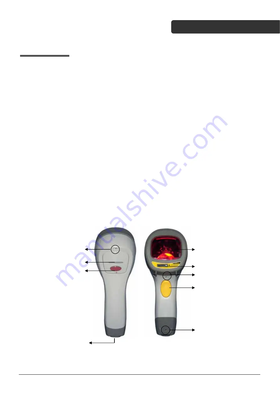
Product Overview  


Buzzer 

Exit Window 

LED Indicator 

Object Detector 

Function 

button 

Buzzer 

Scan Trigger 

Pin Hole 

Cable 

Connection 


Z-3060 Service Guide Ver 1.0 Updated 04/20/2011 

5 / 14

Summary of Contents for Z-3060

Page 1: ...d Omnidirectional Laser Scanner Service Guide Revision History Changes to the original manual are listed below Version Date Description of Version 1 0 April 20 2011 Initial release 1 1 Jan 11 2013 Updated scan engine ...

Page 2: ...f any kind is made in regard to this material including but not limited to implied warranties of merchantability or fitness for a particular purpose We are not liable for any errors contained herein nor incidental or consequential damages in connection with furnishing performance or use of this material No part of this document may be reproduced transmitted stored in a retrieval system transcribed...

Page 3: ...ng scanner should be disconnected from its power source immediately Adjustments Do not attempt any adjustments or alteration of this product Do not remove the protective housing of the scanner There are no user serviceable parts inside Optical The use of optical instruments with this product will increase the eye hazard Optical instruments include binoculars magnifying glasses and microscopes but ...

Page 4: ...ts Preface 2 Important Notice 2 Table of Contents 4 Introduction 5 Product Overview 5 Scanner Parts 6 Take Apart 7 Before You Start 7 Important Instructions 7 Tools to Prepare 7 Z 3060 Service Guide Ver 1 0 Updated 04 20 2011 4 14 ...

Page 5: ...ace The reading status can be checked with the LED indicator and buzzer The scanner operates with 5VDC from Host or external power supply unit The scanner includes key features as Button switch in between omnidirectional and single line scanning capability ideal for increasing your operating efficiency Powerful 20 line scan pattern yields 1400 scans per second for omnidirectional scanning 74 scans...

Page 6: ...apping screw M2 8 0mm round Philips head 4 7 600 430600 051 Bottom cover 1 8 560 130510 691 Trigger 1 9 613 306004 201 IR board assembly 1 10 563 100000 031 Opto Interrupter base 1 11 684 100000 301 Dust cover 1 12 863 306002 502 Scan engine 1 13 031 005010 600 10 pin FFC cable 1 14 031 006508 000 8 pin FFC cable 1 15 613 306002 202 LED board assembly 1 16 613 306008 201 Magnetic SW board assembly...

Page 7: ...ely before you begin Follow all instructions Heed all warnings Tools to Prepare Philips screwdriver Soldering iron Please follow these steps to take apart Z 3060 1 Remove the bottom cover from the scanner 2 Remove the front cover of the scanner Z 3060 Service Guide Ver 1 0 Updated 04 20 2011 7 14 ...

Page 8: ...rews pointed in red arrows 4 Separate the top case from the bottom case and remove the FFC cable as shown in red square 5 Remove the FFC cable from the scan engine in red square Z 3060 Service Guide Ver 1 0 Updated 04 20 2011 8 14 ...

Page 9: ...red square from the main board 7 Remove the module jack adapter by lifting it upward 8 Remove the cables connected to IR board assembly and buzz board assembly in red squares from the main board Z 3060 Service Guide Ver 1 0 Updated 04 20 2011 9 14 ...

Page 10: ...ove the screws from the LED board as pointed in red arrows 10 Lift the main board assembly upwards to remove the main board assembly 11 Remove the trigger rubber seal Z 3060 Service Guide Ver 1 0 Updated 04 20 2011 10 14 ...

Page 11: ...ase note that plastic rods will be damaged and hot glue will be needed to install the new buzzer board 13 Gently bend the snatch pins on the trigger inwards as illustrated to remove the trigger Be careful not to break the pins 14 Remove the screws on the IR board assembly and remove the IR board assembly Z 3060 Service Guide Ver 1 0 Updated 04 20 2011 11 14 ...

Page 12: ...rrupter base from the IR board 16 Remove the screws from the magnetic SW board assembly and remove the magnetic SW board assembly 17 Remove the screws from the LED board on the top case Z 3060 Service Guide Ver 1 0 Updated 04 20 2011 12 14 ...

Page 13: ...8 Remove the LED board and the connector cable 19 Remove the FFC cable from the buzzer board assembly 20 Remove the LED logo trigger rubber seal from the top case Z 3060 Service Guide Ver 1 0 Updated 04 20 2011 13 14 ...

Page 14: ...lve the plastic rods pointed in red arrows using a soldering iron and remove the connector cable Please note that plastic rods will be damaged and hot glue will be needed to install the new buzzer board Note To assemble the scanner start from the last step and work your way backwards and go over every step slowly ...

Reviews: