background image

28

User’s manual

EN

INITIAL START UP – AUTOMATIC MODE

The automatic cycle is started during the initial start-up or after a period of inactivity.

1.  Check that the height of the lawn surface to mow is compatible with the proper functioning of the robot (see “Technical 

Specifications”).

2.  Adjust the cutting height as desired (see “Adjustment of Cutting Height).
3.  Check that the work area has been correctly marked and that there are no impediments to the regular functioning of the robot 

as indicated in the section “Preparation and Marking the Boundaries of the Work Areas” and following sections.

4.  Position the robot inside the charging station.
5.  Press the "ON/OFF" button and wait a few seconds for the robot to turn on completely. Follow the instructions on the display 

and enter the password if prompted.

6.  If starting the robot for the first time, it is necessary to program the settings. However, if starting the robot after a long period 

of inactivity, check that the programmed functions correspond to the actual condition of the lawn to be mowed (e.g. addition 

of a pool, plants, etc.) (See “Programming Mode”).

7.  After a few seconds, the message “CHARGING” will appear on the display.
8.  The robot starts to mow the lawn according to the modes programmed.
9.  Check there are no large puddles after a heavy rain, otherwise the area must be put in order or make sure the robot is in 

"Pause".

ROBOT SAFETY STOP

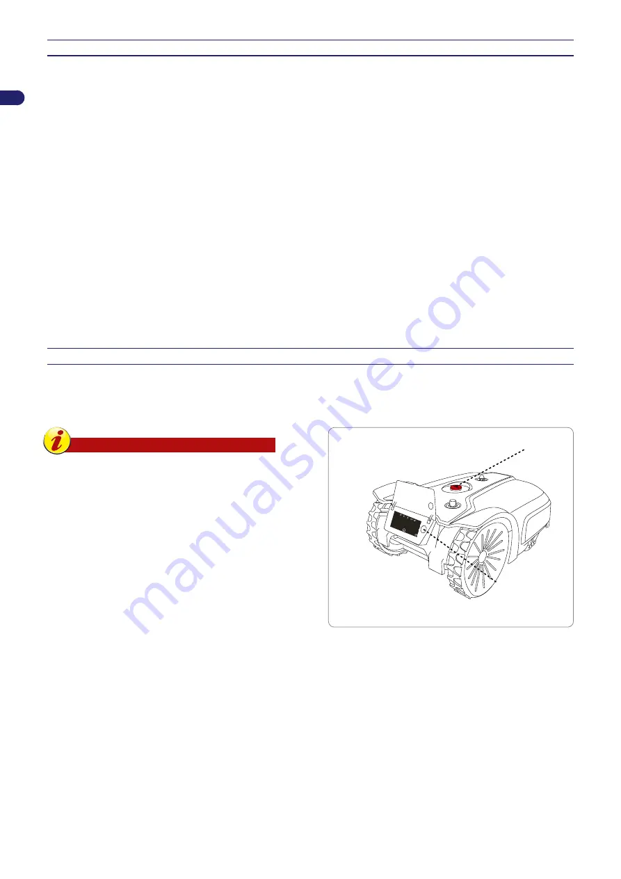
During use, it may be necessary to stop the robot. In normal conditions, the robot can be stopped with the “STOP” key. In case 

of danger or when performing any maintenance, it is necessary to stop the robot in safe conditions in order to prevent the blade 

from accidently starting. First press the “STOP” button and then the "ON/OFF " button. Disconnect the power plug from the 

electrical outlet.

Important

The robot safety stop is necessary during 

maintenance and repairs (for example, blade 

replacement, cleaning operations, etc.).

To start, proceed as indicated:


-

position the robot inside the cutting area;


-

press the "ON/OFF" button to turn on the robot and run the 

start-up procedure again.

If  the  robot  is  started  up  outside  of  the  cutting  area,  the  blade 

motor will not start and after briefly searching for the signal, the 

robot will show "OUT OF BORDER" on the display. Press "ON/

OFF", position the robot inside the cutting area and carry out the 

start up procedure again.

ON/OFF

STOP

.................................

....

......................

10:3

0

Summary of Contents for PRO TECH35 i

Page 1: ...TECH35 i...

Page 2: ...c mode 28 Robot safety stop 28 Use of the robot in closed areas with no charging station 29 Visualising the display during the work phase 30 Prolonged inactivity and restarting 30 Battery charging aft...

Page 3: ...uick reference Some information and illustrations contained in this manual may not perfectly correspond with the appliance in your possession however this does not affect its functioning The Manufactu...

Page 4: ...he instructions on operation maintenance and repair When using the robot make sure there is no one in the working area in particular children the elderly or disabled and pets Otherwise program the rob...

Page 5: ...m are not worn or damaged Make sure that all the nuts bolts and screws are tightened to ensure that the robot is in good working condition If the robot starts to vibrate abnormally during use press ST...

Page 6: ...the working area especially children elderly or disabled people and pets Keep children pets and other people at a safe distance when the machine is functioning To prevent that risk we advise scheduli...

Page 7: ...ions of a trimmed lawn 20 in proximity of the outside edge or perimeter wire Ambient operating temperature Max C ROBOT 10 14 F Min 50 122 F Max CHARGING STATION 10 14 F Min 45 113 F Max BATTERY CHARGE...

Page 8: ...d to work on more than one area a primary area and secondary areas according to the specifications of the various models During operation the robot trims the area marked off by the perimeter wire When...

Page 9: ...sensor 4 Battery 5 Handle 6 Cutting blade 7 Perimeter wire coil 0 8 Pegs 20 9 Power cord for the power supply unit 10 Power Supply unit 11 Charging station 12 Transmitter 13 User manual 14 Key for adj...

Page 10: ...ing system The supply circuit shall be protected by a residual current device RCD with a tripping current of not more than 30 mA Important It is advisable to install the unit in a cabinet for electric...

Page 11: ...h out the excess cord going from the charging station to the power supply unit Do not shorten or lengthen the cord NO NO OK OK NO NO The incoming section of the wire must be straight and aligned perpe...

Page 12: ...o the charging station Follow wire This method of re entry to the charging station commands the robot to follow the perimeter wire positioning its wheels on either side of the wire If this method is a...

Page 13: ...running into the perimeter wire on the opposite side Arrange the wire for quick re entry in a point where there is at least 200 cm 78 74 of straight wire in front of the station and at least 150 cm 5...

Page 14: ...n Therefore it necessary to check carefully the lawn conditions and to respect the limits If the perimeter wire is laid on the sloping more than 20 the robot may depart from it to move more easily not...

Page 15: ...be indicated below from any objects outside the lawn therefore the necessary space for passing must be 140 cm 55 12 if there is a wall or hedge on both sides If this passage is very long the width sh...

Page 16: ...nterferences to the signal of the perimeter wire 30 cm 11 81 30 cm 11 81 5 cm 1 97 30 cm 11 81 If an obstacle is present inside or outside the work area such as a kerb or wall lay the perimeter wire a...

Page 17: ...p edges present inside the work area do not need to be delimited The robot hits the obstacle and changes direction If you don t want the robot to knock into the obstacles and for its safe and silent o...

Page 18: ...supplied making sure there is a maximum distance of around 100 cm 39 37 inches between each peg The wire must be in contact with the ground to prevent it from being damaged by the robot before the gra...

Page 19: ...mains power Position the power supply unit in an area that cannot be reached by children For example at a height above 160 cm 63 Do not shorten or lengthen the cable getting to the charging station wr...

Page 20: ...7 Connect the power cord E of the charging station N to the power supply unit A 8 Connect the plug of the power supply unit A to the electrical outlet 9 If the LED of the transmitter flashes the conn...

Page 21: ...protective gloves to prevent injuries to your hands 1 Turn over the robot and position it so as not to ruin the hood 2 Turn the bracket E in a clockwise direction with the key provided 3 Lift or lower...

Page 22: ...ration shows the location and function of the controls on the machine STOP STOP Press to stop the robotic mower safely Only use in case of imminent danger and to perform maintenance on the robot This...

Page 23: ...See chapter Menu Settings Programming Mode Robot in the garden Re entry Immediately returns to the charging station 10 30 Returns to the charging station and resumes the next work cycle according to t...

Page 24: ...nd the time in the 24 hour format follow the prompts in the display to set up the robot for the first time Once the initial set up process has been completed you can access the menu settings to change...

Page 25: ...settings press Daily schedule A1 A2 A3 A4 1 2 3 4 5 6 7 8 9 0 T1 T4 T3 T2 09 15 10 45 WORK NG AREAS SCHEDULE BORDER CUT A5 A6 A7 A8 10 30 primary area clockwise direction anti clockwise direction sec...

Page 26: ...to the section Re entry method to the charging station With the remaining parameters the robot returns to the charging station while maintaining the approximate distance set from the perimeter wire Th...

Page 27: ...ance required by the robot to reach the inside of the area by following the perimeter wire To ensure that the robot starts working inside the desired area it is recommended to use the middle of the wo...

Page 28: ...nd messages Allows setting the date and time of the robot Allows setting the unit of measurement of the distances and areas Allows turning the sound alerts on and off This allows setting a correction...

Page 29: ...See Programming Mode 7 After a few seconds the message CHARGING will appear on the display 8 The robot starts to mow the lawn according to the modes programmed 9 Check there are no large puddles after...

Page 30: ...nce of 100 cm 39 37 in from the perimeter wire and from any other obstacles 2 Press the ON OFF button and wait a few seconds for the robot to turn on completely Follow the instructions in the display...

Page 31: ...functioning checking and if necessary replacement of any worn parts such as the cutting blade the brushes only in robots equipped with brushed motors checking of the battery capacity if necessary the...

Page 32: ...owth of the grass do not use the robot to mow grass which is 1 cm 0 40 higher than the cutting blade In case of high grass lift the cutting blade and then lower it gradually on the following days if t...

Page 33: ...maintenance Reference Weekly Blade Clean and check the efficiency of the blade If the blade is bent or very worn replace it See Robot Cleaning See Blade Replacement Battery charging knobs Clean and re...

Page 34: ...mage the electric and electronic parts Warning Caution In order to avoid irreversible damage to the electric and electronic components do not immerse the robot partially or completely in water because...

Page 35: ...and restart the robot see Start up Automatic mode Electric motor failure Have the motor replaced or repaired by your nearest authorised service centre Grass too high Increase the cutting height see Ad...

Page 36: ...ocked or obstructed by any objects Clean and eliminate any residual grass under the body shell which may obstruct the sensors see Robot cleaning No Signal appears on the display The perimeter wire is...

Page 37: ...prevent injuries to your hands Unclog the blade The robot was started in the presence of obstacles fallen branches forgotten objects etc Stop the robot safely see Robot Safety Stop Remove the obstacl...

Page 38: ...horised service centre BLADE REPLACEMENT 1 Stop the robot safely see Robot Safety Stop Important Use protective gloves to prevent injuries to your hands For replacement use only the original blade sui...

Page 39: ...ric and electronic equipment have potentially harmful effects on the environment and people s health so the user has a fundamental role in contributing to reuse recycling and any other way of recoveri...

Page 40: ...tic fields EN 55014 1 2017 emission EN 61000 3 2 2014 and EN 61000 3 3 2013 emission EN 55014 2 2015 immunity EN 50419 2006 WEEE Equipment marking ETSI EN 301 489 1 V2 1 1 Electromagnetic compatibilit...

Page 41: ...must be packed in its original packaging and accompanied by a copy of the invoice or purchase receipt including the date of purchase serial number and description of the problem CONDITIONS AND LIMITAT...

Reviews: