background image

SP230/SP230-S5 

2x2 PtP/PtMP 802.11ac Wave 2 Outdoor Access Point 

QSG


5  

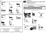
Powering the Access Point 

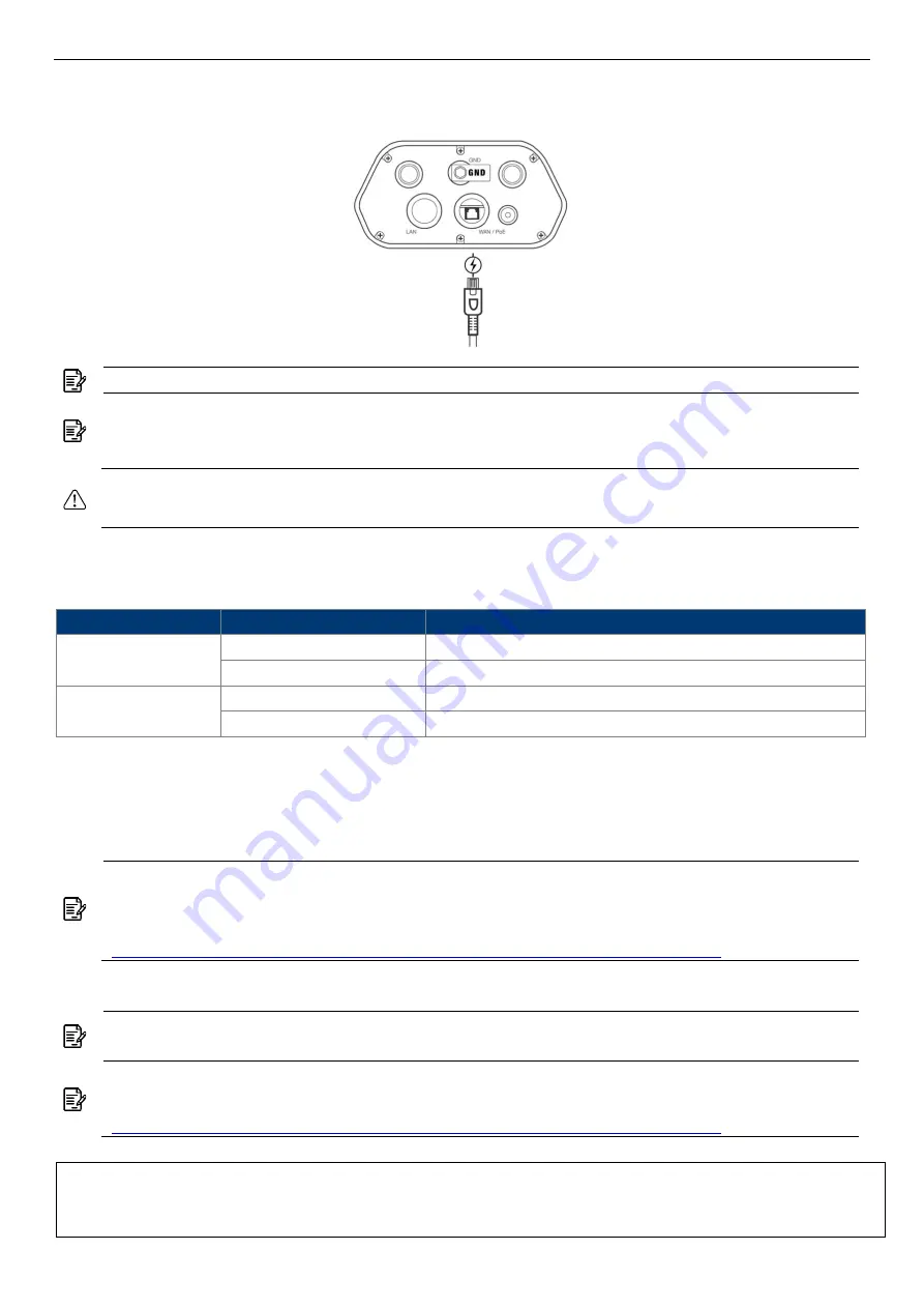
Connect the PoE cable into the WAN/PoE IN port of the device. 


Warning:

 Do 

NOT

 attempt to connect any 

non-PoE

 devices to LAN port and make sure 

the input power should comply with PoE Out standard. 


LED Indicator 

Color 

Behavior 

Description 

Red 

Steady 

Initializing 

Flashing 

Power / system on 

Green 

Steady 

Ethernet connection detected 

Flashing 

No Ethernet connection detected 


Access Point Configuration 

The SP230 default AP mode is TAP mode, which obtains IP addresses from DHCP Option 43 

protocol. The SP230-S5 is FAP mode. 


Note: 

In TAP mode, the AP must be able to go with wireless LAN controllers (WLCs) for 

bulk configuration and performing other commands of access points. Please refer to WLC 

QSG for settings first, then go back to finish the AP configuration. 

https://www.zcom.com.tw/index/downloads?keyword=&meterial_type=49


Step 1.


Power on the AP. As the status of LED indicator from flashing change to steady green, the 

connection is successful. 


Note: 

Please make sure DHCP is enabled on the network once accomplished WLC 

settings. The access point must receive its IP address through DHCP. 


Note: 

Switching from DHCP to assign a static IP address or DNS and L2 discovery mode 

to the access point, please refer to the user manual for more information. 

https://www.zcom.com.tw/index/downloads?keyword=&meterial_type=25


If the access point cannot connect to WLC by DHCP broadcast, please refer to the following 

optional settings.


Optional: Set up a static IP address 


Note:

 Please wait for 5-10 seconds while powering on. 


Note:

 For PoE Out applications, the LAN port provides DC 48V, Max. 208mA, and up to 

10W power supply. The positive side of the 48V is connected to pin 4 and 5, the negative 

side is connected to pin 7 and 8.  

Summary of Contents for SP230 Series

Page 1: ...SP230 SP230 S5 2x2 PtP PtMP 802 11ac Wave 2 Outdoor Access Point QSG Page i...

Page 2: ...e cable into a proper length strip the cables on both ends and crimp the wires into RJ45 connectors It is the professional installer s responsibility to follow local country regulations including oper...

Page 3: ...re the flat head screws will be attached Insert two flat head screws into two dimensional mounting bracket and tighten them approximately Note The pole supported bracket can accommodate up to 6 cm 2 3...

Page 4: ...Anti theft Steel Rope Optional accessory_SP CBM5 Insert three anti theft screws included in the packaging to the device through the mounting bracket Securely tighten these three screws Attach the cla...

Page 5: ...level 4 An excellent grounding system guarantees the stable operation of device as well as to protect device from lightning interference and electrostatic discharges 5 If installed outdoors the device...

Page 6: ...s first then go back to finish the AP configuration https www zcom com tw index downloads keyword meterial_type 49 Step 1 Power on the AP As the status of LED indicator from flashing change to steady...

Page 7: ...g box appears click OK Yes to proceed Step 6 When login page appears enter the following Username root Password password Step 7 Click login Customizing the Wireless Settings On the Web interface menu...

Page 8: ...1000 Mbps port Antenna SP230 2 4GHz Embedded 5dBi omni antennas 5GHz Embedded 5dBi omni antennas SP230 S5 2 4GHz Embedded 5dBi omni antenna 5GHz Embedded 11dBi directional antennas Power Supply DC 48V...

Page 9: ...treams It is your responsibility to dispose of this and other electric and electronic equipment via designated collection facilities appointed by the government or local authorities Correct disposal a...

Page 10: ...wo dimensional mounting bracket Pole supported bracket Intermediate steel plate Two flat head screws Four self tapping screws Four screw anchors Four machine screws M4 Four machine screws M5 V V SP WP...

Reviews: