background image


35 


Warning: Changes or modifications to this device not expressly approved by Zaxcom Inc. could void the user’s authority to operate the equipment. 


NOTE: This equipment has been tested and found to comply with the limits for a Class B digital device, pursuant to Part 15 of the FCC Rules. 
These limits are designed to provide reasonable protection against harmful interference in a residential installation. This equipment generates, 
uses, and can radiate radio frequency energy and, if not installed and used in accordance with the instructions, may cause harmful interference 
to radio communications. However, there is no guarantee that interference will not occur in a particular installation. If this equipment does 
cause harmful interference to radio or television reception, which can be determined by turning the equipment off and on, the user is 
encouraged to try to correct the interference by one or more of the following measures: 

• Reorient or relocate the receiving antenna. 
• Increase the separation between the equipment and receiver. 
• Connect the equipment into an outlet on a circuit different from that to which the receiver is connected. 
• Consult the dealer or an experienced radio/TV technician for help. 


RF Exposure: 
This equipment complies with FCC radiation exposure limits set forth for an uncontrolled environment. This equipment is in direct contact with 
the body of the user under normal operating conditions. This transmitter must not be co-located or operating in conjunction with any other 
antenna or transmitter. 


Under Industry Canada regulations, this radio transmitter may only operate using an antenna of a type and maximum (or lesser) gain approved 
for the transmitter by Industry Canada. To reduce potential radio interference to other users, the antenna type and its gain should be so chosen 
that the equivalent isotropically radiated power (e.i.r.p.) is not more than that necessary for successful communication. 


Conformément à la réglementation d'Industrie Canada, le présent émetteur radio peut fonctionner avec une antenne d'un type et d'un gain 
maximal (ou inférieur) approuvé pour l'émetteur par Industrie Canada. Dans le but de réduire les risques de brouillage radioélectrique à 
l'intention des autres utilisateurs, il faut choisir le type d'antenne et son gain de sorte que la puissance isotrope rayonnée équivalente (p.i.r.e.) 
ne dépasse pas l'intensité nécessaire à l'établissement d'une communication satisfaisante. 


This radio transmitter (contains the module PR6-XRT) and has been approved by Industry Canada to operate with the antenna types listed 
below with the maximum permissible gain and required antenna impedance for each antenna type indicated. Antenna types not included in 
this list, having a gain greater than the maximum gain indicated for that type, are strictly prohibited for use with this device. 


Quarter Wave Whip Antenna, 5.19dBi gain, 50 Ohms 


Le présent émetteur radio (PR6-XRT) a été approuvé par Industrie Canada pour fonctionner avec les types d'antenne énumérés ci-dessous et 
ayant un gain admissible maximal et l'impédance requise pour chaque type d'antenne. Les types d'antenne non inclus dans cette liste, ou dont 
le gain est supérieur au gain maximal indiqué, sont strictement interdits pour l'exploitation de l'émetteur. 


Quarter Wave Whip Antenna, 5.19dBi gain, 50 Ohms 


NOTICE:


Most users do not need a license to operate a wireless microphone system. Nevertheless, operating a microphone system without 
a license is subject to certain restrictions: 

the system may not cause harmful interference, 

it must operate at a low power level (not in excess of 50 milliwatts), 

it has no protection from interference received from any other device. 

 
Purchasers should also be aware that the FCC is currently evaluating the use of wireless microphone systems, and these rules are 
subject to change. For more information, call the FCC at 1-888-CALL-FCC (TTY: 1-888-TELL-FCC) or visit the FCC’s wireless 
microphone website at: 

www.fcc.gov/cgb/wirelessmicrophones.

To operate wireless microphone systems transmitting with 

greater than 50mW of radiated power, you must qualify as a Part 74 user and be licensed.


This alert does 

NOT

 apply to Part 74 users


Summary of Contents for TRXLA3

Page 1: ...1 USER MANUAL Published December 2018 Firmware Version THD 218 TRXLA3 The Future Of Wireless Is Here...

Page 2: ...ENABLE 10 TRANSMIT MENU 11 UHF TRANSMITTER POWER LEVEL SET 11 UHF TRANSMIT MODULATION SET 11 POWER ROLL MODE 11 TRANSMITTER DISABLE RECORD ONLY MODE 12 RECORD MENU 13 SD CARD FORMAT 13 PLAYBACK CONTR...

Page 3: ...E TRXLA3 FIRMWARE 26 UPDATING ERX FIRMWARE WITH A TRX TRANSMITTER 26 UPDATING QRX FIRMWARE WITH A TRX TRANSMITTER 27 INPUTTING AUDIO 28 RECOMMENDED MICROPHONES 28 WIRING DIAGRAMS 28 TWO WIRE MICROPHON...

Page 4: ...Press and hold while in the transport control screen will advance to the next segment Press it while in the home screen will display the group and unit code and the time left on the card 6 DEC Stop Ke...

Page 5: ...inger contacts are facing you and pointing down toward the slot Insert the card into the slot and press it down until you here a slight click To remove it press the card in until you hear the same cli...

Page 6: ...h shows an approximate percentage of remaining power Audio Meter Displays the modulation of the inputted audio signal If using a stereo transmitter in stereo mode both the left and right audio levels...

Page 7: ...transmitter will lock and the display will indicated that it is LOCKED If this screen is exited before the 5 seconds are up the transmitter will not lock To lock the transmitter before the 5 seconds p...

Page 8: ...cessing and navigating the menu groups From in the home screen press the CARD key three times or hold the MENU key while booting up to access the six menu groups Then pressing the INC or DEC key will...

Page 9: ...is recognized Please note that when using the microphone input connector the audio level of the time code signal needs to be between 30 and 10 dBFS on the unit s meter Any level above 10 may cause cl...

Page 10: ...e code to another device Auto Frame Rate Enable When turned ON the TRXLA3 will automatically set its frame rate to the frame rate that is being transmitted from the ZaxNet transmitter that is feeding...

Page 11: ...200 kHz 100 kHz 6 MHz TV Channel Capacity 15 15 15 30 60 Latency 6ms 3 5ms 6ms 6ms 18ms Compatibility with a 200 Series Receiver 2 Transmitters 2 Transmitters 2 Transmitters 2 Transmitters 1 Transmitt...

Page 12: ...e Will set the TRXLA3 to act as a standalone recorder and will not transmit any audio over UHF This will conserve battery power since the transmitter is disabled Normal TX Mode Will allow the TRXLA3 t...

Page 13: ...no longer recognized by the transmitter or by ZaxConvert a partial format can be done The partial format rewrites the FAT32 file structure and leaves the recorded audio untouched To do a partial form...

Page 14: ...ll stop and FULL will be displayed This setting prevents over writing any portion of the audio LOOP RECORD Once the card is full the new audio will begin over writing the oldest audio on the card Low...

Page 15: ...frequency is the frequency that the TRXLA3 will get its wireless time code and remote control commands on This frequency will need to match the frequency of the corresponding ZaxNet transmitter The Z...

Page 16: ...RXLA3 is assigned a unit code The unit code is a unique number used to identify each TRXLA3 within a particular group This allows individual transmitters within the same group to be independently cont...

Page 17: ...ive ZaxNet and NOT go into transmit mode Therefore no ZaxNet TC and or audio will be transmitted This setting shuts off the ZaxNet transmitter Receive then Transmit mode After boot up the ZaxNet trans...

Page 18: ...hes for ZaxNet time code The settings are NEVER or any interval between 5 and 999 seconds Record Beep Set This menu will only appear if the TRXLA3 is set to transmit TX mode When the record beep is se...

Page 19: ...is turned on and adjusted from this menu The high pass filter range is 70Hz to 220Hz in 10Hz increments 2K Notch Filter The 2K notch filter is useful in removing digital RF interference that can be in...

Page 20: ...1 steps The amount of gain reduction is determined by the compressor ratio setting A compressor ratio for example of 2 0 1 means for every 1 dB above the compressor threshold the gain will be reduced...

Page 21: ...smitter will boot up normally STANDBY MODE The transmitter boots up in low power standby mode The transmitter will be waiting for a manual press the of the MENU key to come up to full power REMOTE STA...

Page 22: ...he battery dies Any interval from 1 to 99 minutes Once the battery indicator starts blink a low battery warning the onboard recorder will continue to record for the time set here then it will close th...

Page 23: ...signal and the codes do not match all that will be heard is white noise or silence So if using encryption it is important to make sure the matching receiver has the same code These two sets of numbers...

Page 24: ...in the metadata of the BWF file Naming the unit aids in identifying the files from several different recorders The maximum name length is 8 characters Any letter or number can be used If desired a sp...

Page 25: ...ormatted in a 3 series transmitter to work properly cards formatted in any other series transmitter will not record properly Please note that regardless of the size of the card the onboard recorder wi...

Page 26: ...ds 8 Upon completion cycle the power and confirm that the transmitter is running the new firmware WARNING Before updating the firmware be sure to insert a fresh set of batteries and do not power down...

Page 27: ...l display waiting for program This indicates the receiver is ready to download the new firmware This can be done to several QRXs so they will be updated at the same time 5 At the transmitter proceed t...

Page 28: ...m recommends the following microphones for use with the TRXLA3 Countryman EMW B3 B6 Sanken COS 11D DPA 4063 Wiring Diagrams The following 3 pin micro LEMO connectors mate with the microphone connector...

Page 29: ...Zaxcom TRXLA3 Wiring Diagrams 29 Stereo Microphone Configuration for TRXLAS Balanced Line Level and time code Input Stereo Line Level for stereo transmitters...

Page 30: ...erating Frequencies 30 Operating Frequencies ZaxNet Remote Control and Time Code 2 403 to 2 475 GHz UHF Audio TRXLA3 5 512 0 MHz to 614 0 MHz Blocks 20 through 23 TRXLA3 6 596 0 MHz to 698 0 MHz Block...

Page 31: ...Zaxcom TRXLA3 Antenna Cutting Chart 31...

Page 32: ...tes Download the latest User Manuals from http zaxcom com support updates Submit Technical Questions at http www zaxcom com submit a technical question Submit information for Repair Services at http w...

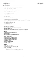
Page 33: ...ic Connector 3 Pin Micro LEMO Mic impedance 6 8 k ADC Bit Depth 24 Bits Time code Reader Generator Clock Accuracy 1 54PPM 1 Frame Out in 6 Hours Time code Type SMPTE Time code Frame Rates 23 98 24 25...

Page 34: ...Product Limitation of Remedies Your exclusive remedy for any defective Product is limited to the repair or replacement of the defective Product Zaxcom may elect which remedy or combination of remedies...

Page 35: ...ada le pr sent metteur radio peut fonctionner avec une antenne d un type et d un gain maximal ou inf rieur approuv pour l metteur par Industrie Canada Dans le but de r duire les risques de brouillage...

Page 36: ...nu dans le pr sent appareil est conforme aux CNR d Innovation Sciences et D veloppement conomique Canada applicables aux appareils radio exempts de licence L exploitation est autoris e aux deux condit...

Page 37: ...37...

Reviews: