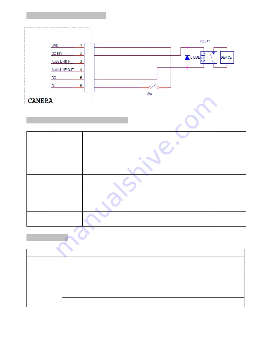
3
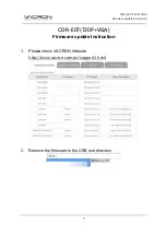
I/O Terminal Block Circuit
I/O Terminal Block Pin Definition
PIN Definition
Description
Max.
V/A
Black Ground
-
Brown +
12VDC
12V
DC
1.2 W
Red Audio
In
Connect the wires of the audio input device to GND
(Pin 1) and AUDIO.IN (Pin 3).
-
Orange Audio
Out Connect the wires of the audio output device to
GND (Pin 1) and AUDIO.OUT (Pin 4).
-
Yellow
Digital
Output 1
Uses an NPN transistor with the emitter connected
to the GND pin. If used with an external relay, a
diode must be connected in parallel with the load
for protection against voltage transients.
100 mA
24V
Green
Digital
Input 1
Connected to GND to activate, or leave floating (or
unconnected) to deactivate.
30V DC
LED Indicator
LED Color
Indication
Network
Blue
Solid blue when network is established.
Blink blue when there is network activity.
Power
Red
Solid red for booting up process
Blue
Solid blue for booting up completion
Purple
Blink purple during: (a) firmware upgrade, (b) reset
button pressed for at least 5 sec to factory default.
Unlit
When reset button is pressed or when power off.
Summary of Contents for D7210
Page 1: ...0 ZAVIO Outdoor IR Mini Dome Quick Installation Guide...
Page 6: ...5...
Page 17: ...16 Application of IP Camera...