background image


Install the hardware and make all cable connection 

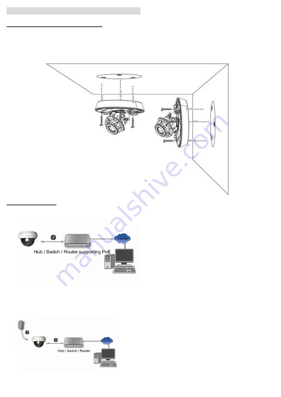
a. Wall mounting and Ceiling mounting 

1. Attach the alignment sticker to the wall/ceiling and drill two pilot holes into it. 

2. Hammer the supplied plastic anchors into the holes. 

3. Align the three holes on the base of camera with the three plastic anchors on the wall and ceiling, insert the 

supplied screws to the corresponding hole and screw them. 


b. Connect all cables 

b1. Power over Ethernet (PoE) 

1.Using a standard RJ-45 network cable, connect the IP Camera to a PoE-enabled Hub / Switch / Router   


b2. Without Power over Ethernet (PoE) connection 

1. Connect the power adaptor to the IP Camera. 

2. Using a standard RJ-45 network cable, connect the IP Camera to a normal Hub / Switch / Router. 


Summary of Contents for D5110

Page 1: ...le Phone See P 9 Access to Internet via Static IP Dynamic IP or both See P 10 Application of IP Camera See P 12 For more information please check the User Manual available in the Software CD or you can download the latest software from http www zavio com Package Contents Camera D5110 D5111 Indoor IR IP Camera Quick Installation Guide Brief product information and quick installation Software CD IP ...

Page 2: ... reset button SD Card Orange Steady orange means SD card ready Flashes orange while accessing SD card Reset When the device is empowered press the Reset Button to reboot the device or hold the Reset Button for 10 seconds to set the settings back to factory default Reset process Press reset button until indicator Unlit steady red booting up process steady blue booting up competition Reset to defaul...

Page 3: ...e of camera with the three plastic anchors on the wall and ceiling insert the supplied screws to the corresponding hole and screw them b Connect all cables b1 Power over Ethernet PoE 1 Using a standard RJ 45 network cable connect the IP Camera to a PoE enabled Hub Switch Router b2 Without Power over Ethernet PoE connection 1 Connect the power adaptor to the IP Camera 2 Using a standard RJ 45 netwo...

Page 4: ... down to your desire tile position c3 Turn the lens module to adjust the image orientation to satisfied angle d To adjust zoom puller and focus puller D5111 only d1 Loosen the zoom and focus pullers anti clockwise to adjust the desire zoom range and focus d2 Lock the zoom and focus pullers by rotating the screw clockwise after get satisfied focus 4 ...

Page 5: ... match the camera s position f3 Fasten the dome cover to the base clockwise and make secure two parts reaching the final position by checking two small dots on the side of housing f4 Slightly adjust dome bubble to final position if needed and double check the camera is properly focused f5 The installation is complete now 5 ...

Page 6: ...ing Intelligent IP Installer please check two setting Select Intelligent IP Installer and follow the installation process to complete the installation a Browser s Internet Properties Security Default Level b Browser s Internet Properties Privacy Uncheck Pop up Blocker 2 Click the Intelligent IP Installer Icon on your desktop The main page will show up listing all active camera and video server dev...

Page 7: ...rst time a yellow information bar appears below the address bar This website wants to install the following add on AxvideoView cab from Zavio Inc 5 Click the information bar and select Install ActiveX control 7 Live video displays in the centre of your web browser 7 ...

Page 8: ...age Change lighting setting The default setting of lighting environment is Auto However you may also select 50 or 60 Hz upon the lighting environment of your country Go to Setting Basic Camera Advance choose the environment setting you wish Auto IRIS setting The default setting of IRIS is open which means IRIS will open all the time If you wish to use auto IRIS function please choose Auto and clic...

Page 9: ...target distance and view angle If you wish to use wide view angle and shorter target distance please set level1 otherwise please set level 2 5 Threshold Threshold value can be set according to applied environment The default value of dark is 95 which means ICR and IR will switch to night mode when the environment is5lux On the other hand the default value of bright is 80 which means ICR and IR wil...

Page 10: ...stablished by inputting the cameras IP information within the Information section Please go to Setting Basic Network Information b Internet Connectivity of the IP Camera can be established through PPPoE Point to Point Protocol over the Ethernet by inputting the username and password from your Internet Service Provider ISP within the PPPoE section Please go to Setting Basic Network PPPoE Note 1 Ple...

Page 11: ...a UPnP Internet Gateway Device IGD turn on the UPnP function within the UPnP section Please go Setting Basic Network UPnP Note If you turn on the UPnP Port Forwarding function RTSP Real Time Streaming Protocol Port information will change to the illustrated value below c2 If your router is not a UPnP Internet Gateway Device please setup Port Forwarding or Port Mapping Note 1 Home Routers manufactu...

Page 12: ...Application of IP Camera 12 ...

Reviews: