background image

ZA-725 User Manual

16

ZA-725 User Manual

15

PROGRAMMING (OPTIONAL)

A programming cable is needed to program different channels or functions on 
the ZA-725. The programming cable links the radio to USB port on a PC or 
laptop. 

USB installation: 

USB cable driver software for your computer operating system is available 
for free downloading from www.zartek.co.za or from the cable manufacturer 
website Prolific (driver for PL2303 USB-Serial cable). Install the correct 
software and plug-in the cable to the PC. The computer should locate the 
cable and configure it automatically. You can check that the cable is working 
by locating it in DEVICE MANGER > PORTS > PROLIFIC USB – SERIAL 
COMM PORT.

Software installation:

Programming software for the ZA-725 is available for free download from 
www.zartek.co.za . Install the software on to a PC by following the installation 
steps. Once installation is finished, an icon called “ZA-725 User PC 
Software” will appear on the screen.
Connect the USB cable to the PC and plug-in the twin connector into the 
speaker/microphone jack on the side of the ZA-725 radio. Ensure that there 
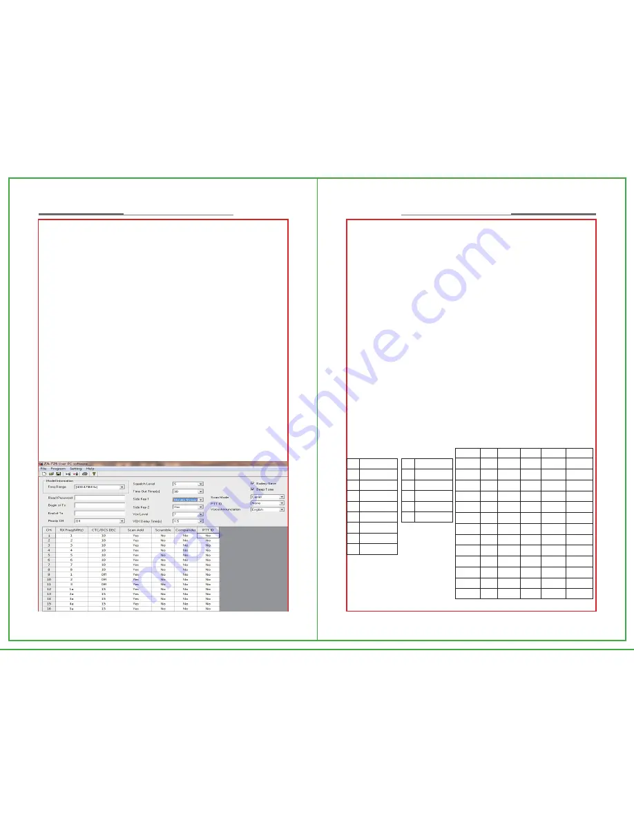
is a charged battery connected to the radio and switch the radio on. Start the 
program and a window will appear. The software automatically finds the 
correct port of the programming cable.

Reading data:

Click on the “READ” left icon (arrow away from radio) and press “OK” to 
begin reading the data from the radio. The RED LED on the radio will flash 
as data is being read. Once loaded, the data can be edited to the appropriate 
channels and settings and then saved or printed for future reference. See 
below for instructions on each function. 

Writing data:

After data is entered, click the “WRITE” right icon (arrow towards radio) to 
program the radio. Press “OK” to begin writing the data to the radio. The 
GREEN LED on the radio will flash as data is being written. Once finished, 
switch the radio off and unplug the cable from the radio. Additional radios can 
be programmed by plugging in the cable to the radio, switching it on and 
following the “WRITE” procedure.

Licence-free bands:

The RX Freq. (MHz) column refers to the frequencies that can be selected on 
the radio.  The 8 frequencies in the 446MHz band are represented by the 8 
channel numbers, 1-8, in the table. These channels correspond to the 
channels on other 446MHz license free radios, such as the Zartek Pro8. The 
5 frequencies in the 464MHz band are represented by the 5 channel 
numbers, 1a-5a, in the second table. These channels correspond to the 
channels on other 464MHz license free radios, such as the Zartek Pro5 or 
ZA200 (model# 21-1860-AF). 

Ch   Freq. (MHz)
1      446.00625
2      446.01875
3      446.03125
4      446.04375
5      446.05625
6      446.06875
7      446.08125
8      446.09375

Ch   Freq. (MHz)
1a     463.975
2a     464.125
3a     464.175
4a     464.325
5a     464.375

Code #   (Hz)  Code #    (Hz)    Code #    (Hz)
    1        67.0    14        107.2      27        167.9
    2        71.9    15        110.9      28        173.8
    3        74.4    16        114.8      29        179.9
    4        77.0    17        118.8      30        186.2
    5        79.7    18        123.0      31        192.8
    6        82.5    19        127.3      32        203.5
    7        85.4     20       131.8      33        210.7
    8        88.5     21       136.5      34        218.1
    9        91.5     22       141.3      35        225.7
   10       94.8     23       146.2      36        233.6
   11       97.4      24       151.4      37        241.8
   12      100.0     25       156.7      38        250.3
   13      103.5     26       162.2

Table of 38 quiet tones

Summary of Contents for ZA-725

Page 1: ...ency Tone Tone is used to add privacy Always match channels exactly when linking to other radios Different channels and functions can be programmable by PC 446 MHz BAND 464 MHz BAND Channel 1 2 3 4 5...

Page 2: ...and quality components have been used in the manufacture of this two way radio to give many years of product use It is designed for rugged outdoor and industrial use to excel in tough environments Th...

Page 3: ...Remove the Antenna Install Remove the Belt Clip Install Remove the Headset Programming Cable Charging the Battery BASIC OPERATION Power On Off Adjust the Volume Select a Channel Transmit Receive Commu...

Page 4: ...For safety reasons it is important that the user is aware of and understands the potential hazards common to using any transceiver To clean the radio wipe with a soft cloth dampened with water Never u...

Page 5: ...sed of correctly 3 Never attempt to disassemble the battery pack Notices 1 Only charge the battery when the ambient temperature is between 5 40 2 Please turn off the radio when the battery is charging...

Page 6: ...is below 0 A spare battery may be necessary in cold weather Please keep the cold batteries as these batteries will work under room temperature 2 If the battery contact is dusty it may influence its no...

Page 7: ...off the radio 2 After switching on the radio turn the knob clockwise to increase volume and turn counter clockwise to decrease volume Press SK1 or SK2 key to enable the specific function which has be...

Page 8: ...o the charger cradle The Red and Green LEDs will flash briefly GETTING STARTED Install Remove the Battery Installing Battery Pack Align the battery pack with the grooves on the back chassis of the rad...

Page 9: ...after some time and the status of flashing Red LED will change to being continuously ON If however the battery is damaged the status of the flashing Red LED will not change Charger Status NB Overcharg...

Page 10: ...r the line of sight distances will be Generally you can talk to wherever you can see which is why the coverage in a valley is much less than the coverage from on top of a hill Ensure that there is not...

Page 11: ...d Once loaded the data can be edited to the appropriate channels and settings and then saved or printed for future reference See below for instructions on each function Writing data After data is ente...

Page 12: ...o 1 2 3 4 5 6 7 8 9 10 11 12 Items OFF Monitor Momentary Scan VOX Show Battery Call Ring Emergency Alert Channel Announcement PTT ID Squelch Level Compander Scrambler Remarks No function The radio wil...

Page 13: ...ume The radio will announce which channel of the possible 16 programmed channels has been received This is very useful when monitoring a large number of channels and responding to the correct channel...

Page 14: ...tivity level it will be required to speak loudly into the microphone to activate the radio At high sensitivity a soft voice is all that is required VOX Delay time Once the radio senses a voice and beg...

Page 15: ...a signal Power Selection only in dealer license version Maximum communication range is achieved when the transceiver is set to high power mode whilst lower power settings will save battery life The p...

Page 16: ...antly Communication range is approximately doubled when using the car external antenna Also note that the higher the antenna is placed the further the range GE 295 car kit consists of a magnetic mount...

Page 17: ...to change the tone on all transceivers in your group Channel programming is empty Frequency Range Channel Capacity Frequency Spacing Working Voltage Frequency Stability Operating Temperature Range An...

Reviews: