Series 3 Technician’s Installation and Service Training Manual
Controller Case Mounting Instruction
Series 3 Technician’s Inst
allati
on and Service Training Manual
Contro
lle
r Case Mount
ing Instructi
on
Series 3 C
on
troller M
ou
n
tin
g In
st
ruct
ion
ZAP Series 3
Simply Logical
ZAP Controls
100 Waterloo Blvd. Anglesey Business Park, Littleworth Road, Cannock, Staffordshire, England
UK Contact
011-44-154-387-9444
USA Contact
931-510-4432
USA Tech Support 931-510-4432
via telephone or text
Online
www.zap-uk.com
Warning Electrical
Shock Hazard
To prevent serious injury or death
always ensure power is disconnected
when wiring anything into the ZAP
Controller.
Tools required
Slotted screwdriver, Drill, 6” long Phillips driver bit,
Phillips screwdriver, Appropriate mounting fasteners.
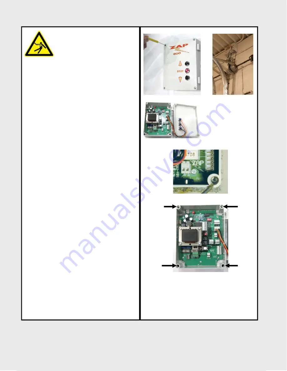
Using a standard screwdriver, insert it into the cover
retaining screws located in each corner of the
controller (Figure A), and loosen the retaining screws
to open the case lid. (Figure B)
Using a general purpose screw with a head diameter
small enough to fit into the corner pillars of the con-
troller, mount the controller a minimum of 5’ above
the ground. Do not mount through the back of the
controller case by removing the circuit board as this
may allow moisture to enter the controller or short
circuit the control board if it touches the fastener
used. Mounting through the back of the controller
case will void the manufacturers’ warranty if damage
occurs. (Figure C & D)
Only mount the controller with the conduit access
knock-out or pre-drilled access holes pointed down.
Only use the knock-out hole to introduce conduit or
wiring into the controller. Moisture can and will
condense in conduit due to the warmth generated by
the controller. If the controller is mounted upside
down and conduit is not used, any liquid spilled on
top of the controller can enter into the controller and
drip the board causing a short circuit. Introducing
conduit in any fashion other than from the bottom of
the controller will void the manufacturers’ warranty if
damage occurs.
You are not limited to mounting the controller at the
five foot height. The controller may be mounted high
by the operator or remotely, as long as the distance
away from the operator does not exceed the length
of the provided motor cable. (Figure E)
A remote wall station control may then be run in a
series from the controller. See remote wall station
wiring page.
Figure A
Figure B
Figure C
Figure D
Figure E
17


