11
type. If other types of flue or appliance are fitted en-sure that there is an adequate
supply of air into the room. When the cooker hood is used in conjunction with other
appliances supplied with energy other than electric, the negative pressure in the room
must not exceed 0,04 mbar to prevent fumes being drawn back into the room by the
cooker hood.
4 - INSTALLATION
For easy installation proceed as follows:
4.1 - Fix the wall brackets.
4.2 - Fix the canopy.
4.3 - Connect the hood to the mains supply and ensure that it works properly.
4-4 - Set the hood for recirculation or evacuation.
4.5 - Fix the telescopic metal frame.
4.1 - Fixing the wall brackets (and splashback).
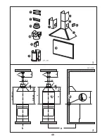
Ref. to Fig. 2a-b
1 - Draw a vertical line on the wall, from the centre of the cooking appliance up to the ceiling,
using a marking pen. This is to ensure the correct vertical alignment of many components.
2 - Fixing the wall brackets No.
1:
a) Put the bracket
I
to the wall, aligning its marked centre across the vertical line, ensuring that
the distance between the centres of the holes and the cooking area is as follows:
Draw a horizontal line on the wall ensuring that the distance from the cooktop is as follows:
1) when the splasback is to be installed:
d
= 265 mm +
H,
where
H
is the height of the
visible part of the splashback; as the splashback can be of different heights, the correct
H
figure
can only be obtained by measuring the actual height of the splashback to be fitted.
2) without splashback
d
= 915 mm minimum.
Note: ensure that the wall bracket (I) is levelled. The hood can be aligned or adjusted in
height by rotating the adjustment screws (see below).
b) Mark on the wall the centres of the two keyholes of the bracket.
3 - Fixing the wall brackets item
2:
a) Place one of the two brackets (item
2 fig. 1
) 15 mm from the ceiling or from a horizontal
line drawn between the top of the adjoining wall cabinets, ensuring that the bracket is level
and mark the centres for the keyhole bracket fixing screws.
b) Place the other wall bracket (item
2 fig. 1
) on the wall at
“X”
distance. This measurement
should be determined by the height of the upper chimney stack and mark the centres for the
keyhole bracket fixing screws.
4 - Pilot drill all the hole positions as marked on the wall using an 8 mm drill and fix the wall
brackets
1
-
2
using the rawl plugs and screws supplied.
5 - Splashback (optional)
When a splashback is to be fitted, the distance between the cooker hood and the cooking
appliances will be determined by the height of the splashback, item
F
. The splashback is to be
installed
before
installing the canopy. If the splashback is to be fixed to the wall using both the
top
and
bottom
fixing holes care must be taken to ensure that the splashback is fitted at the
correct height
before fixing it into position. The fitting should be undertaken by a a
competent person with experience in this type of installation. If the splashback is to be fixed
through
only
the
top
fixing holes proceeds as follows:
a) Put the splashback on the worktop as illustrated in
fig. 2a
; then holding it against the wall to
ensure that it is correctly positioned mark the holes for the top fixing screws on the wall.
Summary of Contents for ZHC 915
Page 11: ...40 b a 2 1 2 1 243_A02 X 115 140 d 915 min 650 min 265 40 X 115 140 d H 265 40 H B B 1 2...
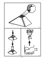
Page 12: ...41 3 4 5...
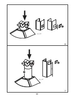
Page 13: ...42 222 6 7...
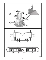
Page 14: ...43 10 9 8...
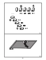
Page 15: ...44 11 12...
Page 16: ...45 13 a c b...
Page 17: ...46 14 15...
Page 18: ...47 16 17...


