background image

20

115

780

420

A

B

C

D

E

Installation

Fig. 1

Positioning the Appliance (Fig. 1)

Note A:

The appliance is designed to be flush fitted with 2mm

clearance at each side to allow for it to be pulled forward

for cleaning etc.

Note B:

The hotplate side trims should be flush with the cabinets

and must not be below. Adjustable levelling feet at the

front and rear are provided on the base of the appliance.

Adjustment is obtained by rotating in or out, the feet at

the front or rear of the appliance from the underside of

the appliance.

A spirit level should be placed on a cake tray on one of

the shelves to confirm that the appliance is correctly

levelled.

The levelling feet fitted to the appliance will achieve a

height to hotplate trims of 900mm-0 + 10.

Note C:

If the appliance is fitted next to a side wall or cabinets

above height of the hotplate trims, then a gap of 115 mm

is required.

Curtains must not be fitted immediately behind the cooker

or within 115 mm of the sides of the cooker.

Note D:

Any wall cabinet or extractor must not be lower than

780mm above hotplate level.

Note E:

Wall cabinets may be fitted in line with the sides of the

base units, providing that the lower edge of the wall

cabinet is a minimum of 420mm above the worktop.

The appliance must be installed in accordance to the

type X (standard EN 60335-2-6).

Therefore  the  appliance  can  not  be  installed  beside

furniture higher than the cooker worktop.

FO  1141

Positioning the Cooker

Caution:

Some soft or badly fitted floor coverings can be damaged

when  the  cooker  is  moved  across  their  surface  for

cleaning. It is advisable to ensure that the floor covering

in the area below the cooker is either securely fixed so

as not to ruck up when the cooker is moved or, if preferred,

removed.

Summary of Contents for ZCM 611

Page 1: ...MIXED FUEL COOKER ZCM 611 INSTRUCTION BOOKLET Please read this instruction booklet before using the appliance GB ...

Page 2: ...Do not operate the cooker with wet hands l Ensure the control knobs are in the OFF position when not in use l When using other electrical appliances ensure the cable does not come into contact with the hot surfaces of the cooker l Unstable or misshapen pans should not be used on the hob burners as unstable pans can cause an accident by tipping or spillage l Never leave the cooker unattended when c...

Page 3: ...P SET TIME Description of the Cooker Splash back Semi Rapid burner Rapid burner Control panel Shelf Ovendoor Semi rapid burner Auxiliary burner Storage drawer Important Safety Information 2 Description of the Cooker 3 Controls 5 Electric Oven 6 Before the First Use of the Cooker 6 24 Hour Clock and Timer 7 Using the Oven 10 Using the Fan Oven 11 Hints and Tips 12 Defrosting 13 Grilling 14 Maintena...

Page 4: ...ty and the environment 2 Slide the two bayonets of the splash back into the relevant supports on the rear edge of the cooker s hob Control Panel 1 Cooker Operation Pilot Light 2 Oven Thermostat Pilot Light 3 Electric ignition push button 4 Back left burner control knob semi rapid 5 Front left burner control knob rapid 9 8 7 6 5 1 2 4 The Oven Cavity Grill element Oven Light Accessories Ovenfan 10 ...

Page 5: ...ller than the recommended size the flame will spread beyond the bottom of the pan causing the handle to overheat As soon as a liquid starts boiling turn down the flame so that it will barely keep the liquid simmering Take care when frying food in hot oil or fat as the overheated splashes could easily ignite If the control knobs become difficult to turn please contact your local Service Force Centr...

Page 6: ...ckaging both inside and outside the cooker before using it Before first use the oven should be heated without food During this time an unpleasant odour may be emitted This is quite normal 1 Set the time of day with the electronic programmer see chapter 24 Hour Clock and Timer 2 Switch the oven function control knob to fan cooking 3 Set the thermostat control knob to MAX 4 Open a window for ventila...

Page 7: ...ress and hold either button to increase or button to decrease the time until the correct time of day on the 24 hour clock is reached To reset the correct time of day 1 Press button and together Then press and hold either button to increase or button to decrease the time until the correct time of day on the 24 hour clock is reached NOTE The increase and decrease control buttons operate slowly at fi...

Page 8: ...mbol will go out NOTE remember to turn the oven function and the thermostat control knob to zero when cooking is over To reset the timer 1 Press button then proceed as described above To cancel the timer 1 Press and release button Then press and hold button the display will count down in one minute intervals to 0 00 The AUTO symbol will go out 2 Release button After a few seconds the display will ...

Page 9: ...see Fig 8 The oven is now locked To unlock the oven 1 Press buttons and at the same time and keep them pressed until OF appears on the display see Fig 9 2 Release the buttons then press button the key symbol will go out and ON will show on the display see Fig 10 Release the button after a few seconds the display will revert to the time of day The oven can now be operated Night dimming function If ...

Page 10: ... affects the way they transmit heat to the food inside them A Aluminium earthenware oven glassware and bright shiny utensils reduce cooking and base browning B Enamelled cast iron anodized aluminium aluminium with non stick interior and coloured exterior and dark heavy utensils increase cooking and base browning Always cook with the oven door closed Stand clear when opening the drop down oven door...

Page 11: ... setting for your personal requirements Cooking Chart Food Shelf Cooking Position Temp C Biscuits 180 190 Bread 210 220 Casseroles 130 140 Cakes Small and queen 160 170 Sponges 160 170 Madeira 140 150 Rich Fruit 130 140 Christmas 130 140 Meringues 90 100 Fish 170 190 Fruit Pies and Crumbles 190 200 Milk Puddings 130 140 Pastry Choux Shortcrust Flaky 190 200 Puff Plate Tarts 180 Quiches Flans 170 1...

Page 12: ...repared Hints and Tips When roasting ensure the meat is cooked thoroughly use a meat thermometer if preferred to check the centre temperature has reached the required temperature see table below Roasting Chart to adjust the temperature by 10 C if necessary Remember to reduce temperatures by about 20 25 C for your own conventional recipes When roasting do use the trivet in the meat tin Fat and meat...

Page 13: ...frosting process Only joints of meat and poultry up to 2 kg 4 lb are suitable for defrosting in this way Refer to the following table for approximate defrosting times The times quoted in the chart should be used as a guide only as the speed of defrosting will depend on the kitchen temperature For example the colder the ambient temperature the longer the defrosting time Defrosting F Chicken 1000 g ...

Page 14: ...s should be placed on the grid in the grill pan to allow maximum circulation of air to lift the food out of the fats and juices Food such as fish liver and kidneys may be placed directly on the grill pan if preferred Food should be thoroughly dried before grilling to minimise splashing Brush lean meats and fish lightly with a little oil or melted butter to keep them moist during cooking Accompanim...

Page 15: ...upports are dishwasher proof If washing them by hand take care when drying them as the enamelling process occasionally leaves rough edges If necessay remove stubborn stains using a paste cleaner The pan support of this cooker is fitted with anti scratch rubber feet These feet are dishwasher proof and should not be removed when cleaning the pan support If the rubber feet become detached from the pa...

Page 16: ...ther suitable for higher temperature 300 C having the following characteristics Voltage 230 240V 50Hz Power 15W Connection E14 Cleaning the Oven The oven should be kept clean at all times A build up of fats or other foodstuffs could result in a fire especially in the grill pan Cleaning materials Before using any cleaning materials on your oven check that they are suitable and that their use is rec...

Page 17: ...u Select a temperature with the thermostat control knob u Select a function with the oven function control knob u Check the light bulb and replace it if necessary see Replacing the Oven Light u The temperature may need adjusting u Refer to the contents of this booklet especially to the chapter Using the Oven u Leave dishes inside the oven no longer than 15 20 minutes after the cooking is completed...

Page 18: ...ironment plus those which are the subject to rental agreements Products of Zanussi manufacture which are not marketed by Zanussi European Guarantee If you should move to another country within Europe then your guarantee moves with you to your new home subject to the following qualifications The guarantee starts from the date you first purchased your product The guarantee is for the same period and...

Page 19: ...NALFLOW RATE m3 h 0 286 0 057 0 190 0 038 0 095 0 028 NOZZLEREFERENCE 119 Adjust 96 Adjust 70 Adjust NOMINALTHERMAL POWERkW 2 8 0 65 2 0 0 45 1 0 0 33 NOMINALFLOW RATE g h 202 43 5 144 29 72 21 5 NOZZLEREFERENCE 86 40 71 32 50 28 NATURAL GAS 20 mbar TYPEOF GAS CHARACTERISTICS LPG GAS 28 30 37 mbar 1 100 mm 1 100 mm VALUE 49 92 MJ Kg VALUE 37 78MJ m3 Ws 50 7 MJ m3 Instructions for the Installer Hob...

Page 20: ...fitted next to a side wall or cabinets above height of the hotplate trims then a gap of 115 mm is required Curtains must not be fitted immediately behind the cooker or within 115 mm of the sides of the cooker Note D Any wall cabinet or extractor must not be lower than 780mm above hotplate level Note E Wall cabinets may be fitted in line with the sides of the base units providing that the lower edg...

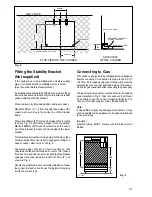
Page 21: ...en measure height from floor level to engagement edge on back of cooker dimension A of Fig 2 Assemble upper bracket to lower bracket so that underside of bracket is dimension A 3mm 1 8 above floor level Re position cooker and check that top bracket engages into cooker back to a depth of 75mm 3 as shown in Fig 2 Should the stability bracket currently installed not allow the cooker to stand correctl...

Page 22: ...en and yellow earth wire to the terminal in the plug which is marked with the letter E or the earth symbol or coloured green and yellow Connect the blue neutral wire to the terminal in the plug which is marked with the letter N or coloured black Connect the brown live wire to the terminal in the plug which is marked with the letter L or coloured red Upon completion there must be no cut or stray st...

Page 23: ... supply and ignite another burner supply The pressure reading should be nominally 20mbar and must be between 17 mbar and 25mbar Turn off the burner supplies Conversion from Natural Gas to LPG It is important to note that this model is designed for use with natural gas but can be converted for use with butane or propane gas providing the correct injectors are fitted and the gas rate is adjusted to ...

Page 24: ...lux Group The world s No 1 choice The Electrolux Group is the world s largest producer of powered appliances for kitchen cleaning and outdoor use More than 55 million Electrolux Group products such as refrigerators cookers washing machines vacuum cleaners chain saws and lawn mowers are sold each year to a value of approx USD 14 billion in more than 150 countries around the world ...

Reviews: