background image

29

INSTALLATION

Installation and Servicing


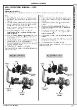
IMPORTANT 

- when filling:

When filling there may be a slight water leak from the air vent therefore electrical connections should be protected.

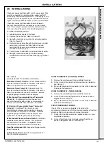
Filling 

1. 

Ensure filling loop is connected and all washers in place. 

2.  Ensure dust cap on auto air vent is slackened off refer to 

frame 60. 

3.  Check the following isolation handles on water connections 

are in the horizontal filling position (blue handle on DHW 

inlet 

A

 and black handle on CH return 

C

).

Note

.  The CH flow isolation valve handle MUST be in the 

vertical position to enable filling.

4. 

Slowly turn the filling loop handle (blue 

B

) to the 

horizontal open position until the pressure gauge reads 

between 1 to 1.5 bar.

5.  Once  the pressure gauge dial reads between 1 to1.5 bar 

turn the filling loop handle (blue 

B

) back to the closed 

(vertical) position.

6.  Turn the CH Return handle (black 

C

) and the DHW Inlet 

handle (blue 

A

) to the open (vertical) position.

7. 

Disconnect the filling loop from the DHW Inlet valve and fit 

the grey cap to the open end.

8. 

Fit the Plug to the free end of the filling loop.

Note open all DHW taps to ensure water is flowing freely-once 

satisfied close all taps.

Top Up 

1. 

Ensure filling loop is connected and all washers in place. 

2.  Ensure dust cap on auto air vent is slackened off refer to 

frame 60. 

3.  Turn the DHW Inlet handle (blue 

A

) to the horizontal 

position.

4. 

Slowly turn the filling loop handle (blue 

B

)  to the 

horizontal open position until the pressure gauge reads 

between 1 to 1.5 bar

5.  Once  the pressure gauge dial reads between 1-1.5 bar 

turn the handle (blue 

B

) on the filling loop back to the 

closed (vertical) position.

6.  Turn the DHW Inlet handle (blue 

A

) to the open (vertical) 

position.

7. 

Disconnect the filling loop from the DHW Inlet valve and fit 

the grey cap to the open end.

8. 

Fit the Plug to the free end of the filling loop.

Note open all DHW taps to ensure water is flowing freely-once 

satisfied close all taps.

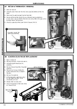
FILLING

A

A

B

C

B

C

24A  CONNECTIONS & FILLING...... CONT

INST

ALLA

TION

Filling Loop

(Blue)

Filling Loop

(Blue)

CH Return

(Black)

CH Return

(Black)

DHW Inlet

(Blue)

DHW Inlet

(Blue)

Cap

Cap

Plug

Plug

Filling 

Loop

Filling 

Loop

Filling Positions shown

Top Up Positions shown

Summary of Contents for ULTRA COMBI 35

Page 1: ...u can be assured conform to the safety and performance specification that we require Do not use reconditioned or copy parts that have not been clearly authorised by Ideal Boilers For the very latest copy of literature for specification and maintenance practices visit our website www zanussi boilers co uk where you can download the relevant information in PDF format April 2016 UIN 214118 A02 ...

Page 2: ...24 2 24 2 Part Load P1 kW 7 9 7 9 Auxiliary Electricity Consumption Full Load elmax kW 0 032 0 042 Part Load elmin kW 0 013 0 013 Standby PSB kW 0 004 0 004 Seasonal Space Heating Energy Efficiency Full Load ƞ4 89 6 89 6 Part Load ƞ1 98 98 Standby Loss Pstby kW 0 005 0 005 Ignition Pign kW 0 0 Emissions NOx mg kWh 26 3 31 2 Annual Energy Consumption QHE GJ 74 9 74 9 Sound Power Level Indoors LWA d...

Page 3: ...s VII Class VIII 1 2 1 5 2 3 4 3 5 5 PRODUCT FICHE The energy efficiency of the package of products provided for in this document may not correspond to its actual energy efficiency once installed in a building as the efficiency is influenced by further factors such as heat loss in the products in relation to the building size and its characteristics Collector Size in m2 Tank Volume in m3 Collector...

Page 4: ...4 Installation and Servicing ...

Page 5: ... vary specification without notice FOR ANY TECHNICAL QUERIES PLEASE RING THE INSTALLER HELPLINE 01482 498663 NOTE BOILER Restart PROCEDURE To reset boiler turn mode knob to restart position and immediately turn knob back to required setting The boiler will repeat the ignition sequence if a heat demand is present NOTES FOR THE INSTALLER Page 2 ERP DATA TABLE DHW information updated ...

Page 6: ...ted Kingdom IE Ireland Countries of destination PMS Maximum operating pressure of water C13 C33 C53 A room sealed appliance designed for connection via ducts to a horizontal or vertical terminal which admits fresh air to the burner and discharges the products of combustion to the outside through orifices which in this case are concentric The fan is up stream of the combustion chamber I2H An applia...

Page 7: ...l heating mode Heat input to be calculated For assistance see Technical Helpline on the back page Page Burner operating pressure n a Central heating flow temp measure and record Central heating return temp measure and record For combination boilers only Scale reducer 14 Hot water mode Heat input to be calculated Max operating burner pressure n a Max operating water pressure measure record Cold wat...

Page 8: ...W plate heat exchanger in a heated condition This only occurs if pre heat knob is in the ON period When there is a demand for CH the heating system is supplied at the selected temperature of between 45o C and 80o C until DHW is drawn off The full output from the boiler is then directed via the diverter valve to the plate heat exchanger to supply a nominal DHW draw off of 30 12 4 l min at 35 o C te...

Page 9: ...tings Regulations or Water byelaws in Scotland The Current I E E Wiring Regulations Where no specific instructions are given reference should be made to the relevant British Standard Code of Practice In IE the installation must be carried out by a Registered Gas Installer RGII and installed in accordance with the current edition of I S 813 Domestic Gas Installations the current Building Regulation...

Page 10: ...notes are intended for general guidance 1 The boiler MUST be installed so that the terminal is exposed to external air LOCATION OF BOILER The boiler must be installed on a flat and vertical internal wall capable of adequately supporting the weight of the boiler and any ancillary equipment The boiler may be fitted on a combustible wall and insulation between the wall and the boiler is not necessary...

Page 11: ...uld also be fitted with a room thermostat controlling the temperature in a space served by radiators not fitted with such a valve When thermostatic radiator valves are used the space heating temperature control over a living dining area or hallway having a heating requirement of at least 10 of the minimum boiler heat output should be achieved using a room thermostat whilst other rooms are individu...

Page 12: ...the flue can be installed from inside the building where wall thicknesses do not exceed 600mm 24 Where the space into which the boiler is going to be installed is less than the length of flue required the flue must be fitted from the outside Installation from inside ONLY b If a core boring tool is to be used inside the building the space in which the boiler is to be installed must be at least wide...

Page 13: ...n additional vessel MUST be installed on the return to the boiler Guidance on vessel sizing is given in Frame 2 Notes a The method of filling refilling topping up or flushing sealed primary hot water circuits from the mains via a temporary hose connection is only allowed if acceptable to the local water authority b Antifreeze fluid corrosion and scale inhibitor fluids suitable for use with boilers...

Page 14: ...kson Electronics Forsyth Road Sheerwater Woking Surrey GU21 5RZ 44 0 8706 015000 Sentinel Performance Solutions The Heath Business Technical Park Runcorn Cheshire WA7 4QX Tel 0800 389 4670 Scalemaster Water Treatment Products Emerald Way Stone Staffordshire ST15 0SR Tel 44 0 1785 811636 Calmag Ltd Unit 3 6 Crown Works Bradford Road Sandbeds Keighley West Yorkshire BD20 5LN Tel 44 0 1535 210320 Ade...

Page 15: ...ensate Internal 229 Siphon Trap 231 Condensate Outlet Connection 301 Ctrl Box Fixings Hings Spring 302 Primary PCB 303 CUI Board 304 Control Thermistor Return 306 Electrode Ignition 307 Electrode Detection 308 Ignitor Unit 309 Thermistor Flow 313 Ignition Lead 314 Control Box Lens 320 Detection Lead 324 Control Box Lid 325 Control Box Front 326 Programmer Insert 401 Heat Engine 503 Wall Mounting B...

Page 16: ...alve Pack 1 Pipe Gas Inlet 2 Washer Gas blue 3 Gas Cock Filling Loop Pack 1 3 8 Top Hat Washer 2 Valve Filling Loop 3 Pipe Filling Loop Return Valve Pack 1 Pipe CH Return 2 Washer CH 3 Valve Return 4 3 8 Washer DHW Pack 1 1 2 Top Hat Washer x2 2 Cap Female 3 Plug Male and Clip 4 Nut G1 2 16 Brass Flat 5 Washer 18 5 x 11 x 11 8 x2 6 Pipe DHW Outlet 7 Pipe DHW Inlet 8 Valve DHW Inlet Accessory Pack ...

Page 17: ... B 1 2 Pack B Contents Non Telescopic A Flue terminal B Flue turret C Rubber terminal wall seal D Cutting Aid E Wall Seal white 8 UNPACKING CONT D A D B C E Note This flue system incorporates a removable flue outlet nose that utilises a push fit location system This enables the installation of deflector high level or balcony outlet flue kits without the removal of the whole B pack terminal The app...

Page 18: ...Both wall faces immediately around the cut hole should be flat 2 Drill 2 mounting holes marked from template with a 7 5mm 8mm masonry drill and insert the plastic plugs provided for the wall mounting plate 3 Locate 2 No 14 x 50mm screws in the wall mounting plate one at each side in any of the 3 holes provided at each side and screw home Ensure mounting bracket is level 13 MOUNTING THE BOILER 1 En...

Page 19: ... supplied in the B Pack has an upper combustion sample point with a screw cap seal and a lower air sample point with an air stopper seal Ensure all caps seals are in place Additional Termination Kits available for use with these B packs Flue Deflector Kit The resistance is the equivalent of 1 metre of flue pipe and therefore must be deducted from any maximum flue length High Level Flue Outlet Kit ...

Page 20: ...00mm long B Pack Telescopic Horizontal Flue Terminal 1000mm long B Pack Telescopic Cut 75mm Minimum Maximum Minimum Maximum Minimum Maximum Minimum Maximum B Pack Standard 171 556 286 484 601 816 526 741 Plus 1 1m D pack 1121 1506 1236 1434 1551 1766 1476 1691 Plus 2 1m D pack 2071 2456 2186 2384 2501 2716 2426 2641 Plus 3 1m D pack 3021 3406 3136 3334 3451 3666 3376 3591 Plus 4 1m D pack 3971 435...

Page 21: ...rminal is upper most 4 Drill a 3 5mm hole through one of the 2 outer side holes in the outer flue section into the inserted outer flue as shown Take care not to pierce the inner plastic flue Fit screw provided 5 Seal the joint on the outer air duct with the tape provided 6 Fit internal and external wall seals see installing flue CUTTING HORIZONTAL FLUE TERMINAL 600MM LONG B PACK 1 Measure the requ...

Page 22: ... refitted 9 When 1st mark is in line with the wall whilst holding the flue firmly push the white wall sealing flange to the wall until the 2nd of the two marks is just visible If the last location mark is clearly passed the white inner wall seal then the outer wall seal will have been dislodged from its mounting and will need to be re fitted 10 Ensure the seam and the outlet terminal are at the to...

Page 23: ...l weather collar ACCESSORIES Flue Duct Extension Kits are available for flue lengths extending beyond 1m These packs contain 1m extension ducts and may be cut to the desired length If the offset vertical option is used an elbow Kit is required Soffit Flue Kit supplied as an optional extra For a full accessories list refer to page 9 Optional Extras Flue duct support Vertical Connector Flue duct sup...

Page 24: ...ate the shaded area of the roof Note The equivalent flue length resistance of the elbow kits are 90o elbow kit 1m 45o elbow kit 0 6m If chimney penetrates dotted area such that A is less than 300mm B shall not be less than 300mm Where two or more vertical fanned draught chimney configurations terminate in close proximity at the same height they shall be separated by at least 300mm Where any one ve...

Page 25: ...ructions provided with the vertical connector kit 3 Secure the vertical connector by applying downward pressure on the connector 4 Position the clamp on the top face of the flue manifold and push it horizontally backwards Locate both clamp lugs into the flue manifold and secure to the flue manifold with the M5 retaining screw 5 Push fit extension duct if required supplied separately into vertical ...

Page 26: ...rnal Drain Connections The use of an externally run condensate drainage pipe should only be considered after exhausting all internal termination options as described previously An external system must terminate at a suitable foul water discharge point or purpose designed soak away If an external system is chosen then the following measures must be adopted The external pipe run should be kept to a ...

Page 27: ...Minimum connection height up to 3 storeys Soil vent stack 450 Boiler with 75mm sealed condensate trap Min Ø 19mm Internal pipe Min Ø 30mm Internal pipe Water weather proof insulation 75 Boilers without 75mm sealed condensate trap must be fitted with a 75mm trap and visible air break Visible air break at plug hole Min Ø 19mm Internal pipe Sink basin bath or shower with integral overflow and 75mm tr...

Page 28: ...e valve blue handle and copper tail to the threaded boss connection ensuring the seal provided is correctly located 2 Fit the DHW outlet pipe tail to DHW outlet connection ensuring the seal provided is correctly located 3 Fit the filling loop provided between the DHW inlet valve and the CH return valve GAS CONNECTION IMPORTANT The gas service cock is sealed with a non metallic blue fibre washer wh...

Page 29: ... and fit the grey cap to the open end 8 Fit the Plug to the free end of the filling loop Note open all DHW taps to ensure water is flowing freely once satisfied close all taps Top Up 1 Ensure filling loop is connected and all washers in place 2 Ensure dust cap on auto air vent is slackened off refer to frame 60 3 Turn the DHW Inlet handle blue A to the horizontal position 4 Slowly turn the filling...

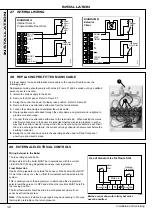
Page 30: ...te isolation of the electrical supply such as a double pole switch having a 3mm 1 8 contact separation in both poles The means of isolation must be accessible to the user after installation WARNING This appliance MUST be earthed A mains supply of 230Vac 50 Hz is required The fuse rating should be 3A All external controls and wiring must be suitable for mains voltage Wiring external to the boiler M...

Page 31: ...F Mechanical Programmable Room Thermostat 24 hr kit Combined 24 hour mechanical timer and room thermostat with wireless communication to receiver unit which fits into control box of the boiler RF Electronic Programmable Room Thermostat 7 day kit Combined 7 day timer and room thermostat with wireless communication to receiver unit which fits into control box of the boiler Features English language ...

Page 32: ...m Stat Optional Frost Stat DIAGRAM A Internal Timer or Programmable Room Stat 3G9561 N L N FROST STAT OPTIONAL ROOM STAT TIMER Room Stat Optional Frost Stat DIAGRAM B External Timer 28 REPLACING PRE FITTED MAINS CABLE If it is necessary to use an alternative mains cable to the one pre fitted then use the following guide Replacement wiring should comply with notes in Frame 31 and be caried out by a...

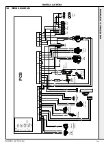
Page 33: ...ain Supply Frost Stat r b bk or bk 1 X1A X1B X1C X2 X3 X5 X6 X8 2 3 4 5 6 1 2 3 4 5 1 2 3 4 5 6 8 7 9 1 2 3 4 1 2 3 4 5 6 X7 1 2 3 4 5 X13 1 2 3 1 2 3 4 5 6 7 8 9 10 11 p bk r bk PCB Earth Timer Link y g br b bk bk b b br y g blue black brown red pink yellow white yellow green grey orange violet b bk br r p y w y g g or v KEY p y bk bk bk b y g br y g y g bk b bk b br bk v y g y g 1 2 3 4 5 1 2 3 ...

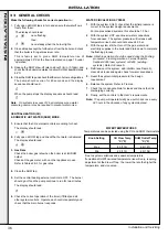
Page 34: ...002 2 Purge air from the gas installation by the approved methods only 31 COMMISSIONING AND TESTING GENERAL Please Note The combustion for this appliance has been checked adjusted and preset at the factory for operation on the gas type defined on the appliance data plate DO NOT adjust the air gas ratio valve Having checked That the boiler has been installed in accordance with these instructions Th...

Page 35: ...eck all external controls are calling for heat CENTRAL HEATING 9 Set the CH temp control C to max and turn the mode knob D to The boiler control should now go through its ignition sequence until the burner is established 10 If the boiler does not light code will be displayed After 5 attempts the boiler will lock out and display fault code constantly Restart the boiler Refer to Frame 34 The boiler ...

Page 36: ... when the burner lights 2 Close all taps except the furthest one from the boiler and check that the boiler is firing at maximum rate This is factory set to give a DHW temperature rise of approximately 35o C at the flow rate stated on page 10 under operation 3 Reduce the DHW draw off rate to about 3 l min 0 7gpm and check that the boiler modulates to deliver DHW at approximately 64o C 4 Close the D...

Page 37: ... fully explained to the householder to ensure the greatest possible fuel economy consistent with the household requirements of both heating and hot water consumption Advise the User of the precautions necessary to prevent damage to the system and to the building in the event of the system remaining inoperative during frosty conditions 4 Explain the function and the use of the boiler heating and do...

Page 38: ...re fully in Frames 38 42 and MUST be carried out in sequence IMPORTANT 6 After completing the servicing or exchange of components always test for gas tightness 7 When work is complete the front panel MUST be correctly refitted ensuring that a good seal is made Do NOT OPERATE the boiler if the front panel is not fitted 8 If for any reason the condensate trap siphon has been removed ensure the trap ...

Page 39: ...the front panel 5 Re tighten the two retaining screws 38 FAN AND VENTURI ASSEMBLY REMOVAL AND CLEANING 1 Disconnect the electrical leads from the fan 2 Remove the clip from the gas control valve outlet and ease the pipe upwards rotate and then ease down to remove 3 Remove the extended nut on the fan mounting bracket 4 Lift off fan and venturi assembly 5 Undo the two M4 screws and release the nozzl...

Page 40: ...burner head is a ceramic plaque construction Care must be taken to ensure that the burner is not placed down upon its face as this may cause damage to the ceramic 6 Brush off any deposits that may be on the ceramic with a SOFT brush 7 Inspect the sealing gasket around the burner for any signs of damage Replace as necessary 40 CLEANING THE CONDENSATE TRAP SIPHON 1 3 2 2 4 4 5 1 Pull off the rubber ...

Page 41: ...n and detection gaps are correct Refer to Frames 48 49 1 Ignition Electrode Flame Detection Reassemble the boiler in the following order 1 Ensure that the condensate trap siphon is full of water 2 Refit the burner ensuring the sealing gasket is correctly positioned and free from damage tighten the 4 fixing screws in the sequence shown below 3 Refit the fan venturi assembly ensuring the retaining t...

Page 42: ...NOT BE OPERATED WITHOUT THE FRONT PANEL FITTED 44 FAN REPLACEMENT 1 Refer to Frame 43 2 Disconnect the electrical leads from the fan 3 Remove the clip from the gas control valve outlet 4 Remove the extended nut retaining the fan mounting bracket 5 Lift and remove the fan and venturi assembly 6 Remove the screw and twist venturi anti clockwise to remove venturi assembly noting the orientation of th...

Page 43: ...order ensuring that the new gas seal supplied is located correctly in the injector housing 10 Check operation of the boiler Refer to Frames 32 33 4 3 3 46 BURNER REPLACEMENT 5 5 6 1 See Frame 43 2 Refer to Frame 44 3 Undo the two screws and remove the sump cover 4 Lift the manifold to clear the bottom sealing gasket and remove manifold 5 Remove the 2 front fixing screws and loosen the 2 rear exten...

Page 44: ...eassemble in reverse order 9 Check the operation of the boiler Refer to Frames 32 33 47 RETURN THERMISTOR RENEWAL 1 Refer to Frame 43 2 Unclip the return thermistor from the return pipe and withdraw it from the boiler 3 Disconnect the electrical lead from the thermistor 4 Reconnect the electrical lead to the new thermistor and reassemble in reverse order ensuring that the thermistor is securely fi...

Page 45: ...ws retaining the detection electrode 5 Remove the electrode 6 Fit the new flame detection electrode using the new gasket supplied 7 Reassemble in reverse order 8 Check the operation of the boiler Refer to Frames 32 33 3 51 GAS CONTROL VALVE REPLACEMENT 1 Refer to Frame 43 2 Unplug the electrical lead connection from the gas control valve 3 Disconnect the earth wire 4 Remove the outlet gas valve cl...

Page 46: ...a Re connect the inline connector block b Ensure that the switched live to the boiler is off and that all DHW taps are shut and that pre heat is switched off c Hold the mode knob in the restart position for more than 10 secs d The display will alternate between d and U and the actuator will move into the mid position e The divertor valve will initially drive all the way out this may cause the spin...

Page 47: ...everse order 10 a Turn power on b Displays 8 blue light on off first digit input second digit input 1st letter appliance type i e 3 0 c c Move knob to required setting standby summer winter Note If no BCC fitted on non programmed board C2 will be displayed The correct BCC for this appliance will need to be fitted 11 Check operation of the boiler Refer to Frames 32 33 3 6 Plastic clip 5 1 Refer to ...

Page 48: ...24 before proceeding to check operation of the boiler 5 Disconnect filling loop Refer to Frame 24 6 Check operation of the boiler Refer to Frames 32 33 CH Circuit Drain CH Flow Gas CH Return DHW Inlet DHW Outlet Filling Loop CENTRAL HEATING CIRCUIT 1 Refer to Frame 43 2 Close all the CH water isolating valves on the boiler inlet 3 To drain the primary heat exchanger circuit Open the drain valve an...

Page 49: ...22mm pipe connection at top of pump chamber and bottom of heat exchanger and remove pipe Refer to Frame 59 no s 5 6 7 5 The automatic air vent head is retained in the pump body with a bayonet connection The air vent head and float assembly is removed by turning the head anti clockwise viewed from above and pulling upwards 6 Reassembly is the reverse of the above Ensure the air vent head o ring sea...

Page 50: ... 1 Refer to Frame 43 2 Drain the boiler Refer to frame 57 3 Remove the condensate trap siphon Refer to Frame 53 4 Remove the electrical plug Refer to Frame 52 5 Place a flat bladed screwdriver in the diverter valve motor body slot provided and ease out the motor Refer to Frame 52 6 Remove the return thermistor electrical connection Refer to Frame 47 7 Remove the pump electrical connections Refer t...

Page 51: ...3 Pull off the two electrical connections 4 Using a suitable tool pull out the metal retaining clip 5 Carefully withdraw the pressure switch 6 Fit the new pressure switch and re assemble in reverse order 7 Refill the boiler 8 Check operation of the boiler Refer to Frames 32 33 3 4 5 66 DHW FILTER DHW FLOW REGULATOR CLEANING REPLACEMENT 3 1 Refer to Frame 43 2 Isolate the DHW supply 3 Turn the hous...

Page 52: ... any sign of damage is evident When replacing the spring clips located on the return pipe connection ensure clip is oriented to correctly match connecting pipe diameters 18 Ensure the trap siphon is filled with water Refer to Frame 53 19 Refill the boiler Refer to Frame 24 20 Check operation of the boiler Refer to Frames 32 33 1 Refer to Frame 43 2 Drain the boiler Refer to Frame 57 3 Remove the f...

Page 53: ... 43 2 Remove the charge point cover 3 Recharge the tank pressure to 0 75 bar 4 Re assemble in reverse order 5 Check operation of the boiler Refer to Frames 32 33 REPLACEMENT 6 Refer to Frame 43 7 Drain the boiler CH circuit Refer to Frame 57 8 Remove the retaining clip on the vessel water connection pipe 9 Support the expansion vessel and unscrew the 2 screws from the securing clamp located on the...

Page 54: ...ETURN THERMISTOR FAULT GO TO FRAME 80 OUTSIDE SENSOR FAULT LOW MAINS VOLTAGE CONTACT ELECTRICITY PROVIDER PCB FAULT REPLACE PCB Restart BOILER NO CH BUT HW OK NO HW BUT CH OK NO DISPLAY GO TO FRAME 82 GO TO FRAME 83 GO TO FRAME 84 If PCB replaced as a spare ensure that the BCC boiler chip card small plastic part is fitted to the PCB otherwise replace PCB ALTERNATING L and 5 5 RESETS WITHIN 15 MINS...

Page 55: ...ame 50 Are these functioning correctly YES Check ignition electrode and associated harness for continuity visual condition and position Refer to Frame 48 Are these functioning correctly NO Check siphon and condensate drain pipe work for blockage and rectify if necessary Boiler now working OK Check wiring connection from gas valve to PCB for continuity If the wiring is OK then replace the PCB NO Re...

Page 56: ...rom gas valve to PCB for continuity If the wiring is OK then replace the PCB NO Replace Spark Generator and Harness as necessary NO Replace Ignition Electrode and associated harness as necessary NO Replace Gas Valve NO Note due to the wave form of the rectified voltage the reading will vary depending on the type of meter used to measure the value In general terms a reading greater than 150V indica...

Page 57: ...t 1 000 1 100 Ohms Is the Thermistor value correct YES Is the wiring securely connected to the low voltage 6 way connector at the front left hand side of the PCB YES Replace PCB Fit a new Thermistor NO Securely connect the wiring to the PCB Is the wiring securely connected to the Flow Thermistor located in the top of the Heat Exchanger YES NO Securely connect the wiring to the Water Flow Thermisto...

Page 58: ...g at the Terminal Block and the PCB Is the wiring securely connected at both the boiler and Outside Sensor YES NO Securely connect the wiring at both the boiler and Outside Sensor NO YES 81 ALTERNATING c AND 2 BCC FAULT BOILER CHIP CARD Is the correct BCC for the boiler securely inserted into the slot at the front left of the PCB identified by the label on the BCC YES NO Securely insert the correc...

Page 59: ...ove the mode knob to the Winter position Are the Timer and the Room Thermostat switched on YES NO Switch the Timer and Room Thermostat On Are the Radiator Valves Open YES NO Open the Radiator Valves Is there 230Vac at A YES NO There is no Voltage from the Timer Room Stat This is not boiler fault Ensure Voltage is supplied to boiler by rectifying external wiring Replace the Divertor Valve Motor A ...

Page 60: ...ow d when a tap is on NO NO YES Are the flow rates correct as per Frame 2 Is the wiring between the PCB and the diverter valve motor connected YES YES Check diverter head fully engaged and clip secured onto waterset YES Is diverter stuck in the CH position YES Check and replace diverter valve actuator head Is Boiler DHW OK NO Change diverter valve motor NO Adjust flow rates to achieve 35º temp ris...

Page 61: ... Boilers Failure to do so could affect safety or performance of this appliance Comprehensive spare parts information and details of approved Ideal Parts Distributors are available on www idealparts com Our Parts team are also available to help with your Ideal Spare Parts enquiries on 01482 498665 When calling and to ensure we can provide you with the most accurate parts information please ensure y...

Page 62: ......
Page 63: ...commissioning checklist completed in full To instigate the boiler guarantee the boiler needs to be registered with the manufacturer within one month of the installation To maintain the boiler guarantee it is essential that the boiler is serviced annually by a Gas Safe registered engineer who has been trained on the boiler installed The service details should be recorded on the Benchmark Service In...

Page 64: ...opriate Building Regulations and then handed to the customer to keep for future reference GAS BOILER SYSTEM COMMISSIONING CHECKLIST CONTROLS Programmable room thermostat Optimum start control Combination Boiler Fitted Fitted Fitted Automatic bypass to system Fitted Boiler interlock ALL SYSTEMS Yes Yes CENTRAL HEATING MODE OR mbar OR mbar Central heating return temperature COMBINATION BOILERS ONLY ...

Page 65: ...ularly and that the appropriate Service Interval Record is completed Service Provider SERVICE RECORD SERVICE 01 AND Where Possible AND Signature SERVICE 02 AND Where Possible AND Signature SERVICE 03 AND Where Possible AND Signature SERVICE 04 AND Where Possible AND Signature SERVICE 05 AND Where Possible AND Signature SERVICE 06 AND Where Possible AND Signature SERVICE 07 AND Where Possible AND S...

Page 66: ...followed e g Gas Safe Register Technical Bulletin TB 008 where chimney flues are in voids The ECGA should be of the correct type as specified by BS 7967 Prior to its use the ECGA should have been maintained and calibrated as specified by the manufacturer The installer must have the relevant competence for use of the analyser Check and zero the analyser IN FRESH AIR in accordance with the analyser ...

Page 67: ...e assembled fixed and supported as per instructions Check that flue and flue terminal are not obstructed Check that no seals e g Those on flue extensions have been displaced during installation Rectify if necessary Turn off appliance and call Technical Helpline for advice The appliance must not be commissioned until problems are identified and resolved If commissioning cannot be fully completed th...

Page 68: ...nussi Ultra Boilers Installer Support Helpline 01482 498663 Customer Helpline 01482 498660 Ideal Boilers P O Box 103 National Avenue Kingston Upon Hull HU5 4JN We reserve the right to change the specifications without prior notice Consumers statutory rights are not affected ...

Reviews: