


DEVICE CONFIGURATION
SOFTWARE UPGRADE
GRM-10 has a default factory settings. Before use, carefully read the manual instruction and make a proper device configuration. In order
to freely manage the configuration settings, the GRM-10 device makes the local and remote configuration possible. The remote configura-
tion allows to manage the settings of the already working GRM-10 device without a physical access to it (for example, to a device that is
installed in the building). The configuration can be done as follows:
a) by means of a mobile phone via text massage (local and remote configuration),
b) by means of the PC application via the Micro USB interface (only the local configuration).
Local configuration by means of a mobile phone
1. Press the PK2 push-button on the front panel.
2. Switch on the power supply and keep the PK2 push-button pressed.
3. Hold the PK2 push-button as long as the LED red diodes LEDP1 and LEDP2 start flashing.
4. Wait until the GRM-10 device logs into the GSM network (LED yellow diode GSM flashes).
5. Adjust the configuration parameters by sending appropriate text messages (see CONFIGURATION COMMANDS).
6. Switch off the power supply from the mains.
Remote configuration by means of a mobile phone
The remote configuration is available only for these telephone numbers that have been added to the so called administrative numbers’ list
by means of the configuration command ADMIN (see CONFIGURATION COMMANDS) during the local configuration (by means of a text
message or a PC application). The remote configuration is possible during a usual device operation if it is “logged in” to the GSM network.
1. Send a text message with a CONFIG MODE content from a telephone number included on the ADMIN list.
2. By receiving the above text message, the GRM-10 device will send back a reply “CONFIG MODE OK’ and will enter the configuration
mode, which is indicated by flashing red LED diodes LEDP1 and LEDP2.
3. Carry out the device configuration in accordance with the CONFIGURATION COMMANDS.
4. Send a TEXT MESSAGE with the CONFIG MODE END content to leave the remote configuration mode.
5. By receiving the above text message, the GRM-10 device will send back a reply “CONFIG MODE END -OK’ and will enter a usual
operation mode
When entering / leaving the remote configuration mode, the outputs’ status remains unchanged.
Configuration by means of the PC application via an MIC RO USB interface
NOTE: Every time before making any changes in the configuration settings by means of the PC application, first read the current configu-
ration of the GRM-10 device. It is necessary not to overwrite or lose the configuration settings implicated by the telephone text message.
1. Start the GRM-10 application on PC.
2. Switch off the power supply to connect the MICRO USB to the GRM-10 device.
3. Wait until the GRM-10 device appears in the operating system to install properly.
4. READ CURRENT GRM-10 DEVICE CONFIGURATION.
5. Carry out / change the configuration adjustments by means of the PC application.
6. In order to save the current configuration of the GRM-10 device, press the “ZAPISZ DO URZĄDZENIA” push-button.
7. Press shortly the PK1 push-button on the front panel of the GRM-10 device (LED yellow diode RS485 switches on for a moment).
8. If the configuration is correct, the application sends back a message ‘CONFIGURATION OK.’ Otherwise the message ‘CONFIGURA-
TION ERROR’ displays.
9. Disconnect the MICRO USB cable from the GRM-10 device.
Saving the configuration to *. zml file
The current configuration can be saved to a ‘*.zml’ file. In order to do it, by means of the application press the “ZAPISZ DO PLIKU’ push-
button and select the proper file place to save it.
Reading the configuration from the *. zml file
The current configuration can be read from the ‘*.zml’ file. In order to do it, by means of the application press the “WCZYTAJ Z PLIKU”
push-button, next choose the correct file place to read it.
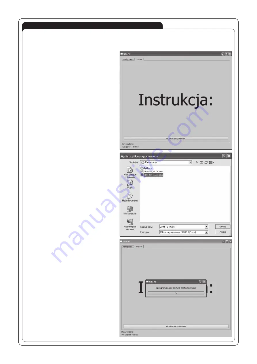
The GRM-10 user has the ability to upgrade the software using the Micro USB interface. It may be necessary in case of an upgrade
release by the producer. Information on the current software can be found on the product website:
http://www.zamelcet.com/pl,263,4537,sterownik_gsm_modulowy_2kanalowy_grm10.html.
The upgrade is carried out by the GRM-10 application on
the PC:
1. After switching off the power supply voltage connect the
GRM-10 device to the PC by means of a USB, Micro B /
USB cable and pressing the PK2 push-button.
2. Start the GRM-10 application and select the UPGRADE
window.
3. Select “Software Upgrade” and then select the latest
version of the GRM-10 software (the *. ZMS) from a
specific location.
4. If the software is successfully updated the application
will show a comment: “The software has been updated”.
5. Press “OK.”
6. Disconnect the USB Micro B / USB A cable.
7. Switch on the power supply.
CONNECTION AND INSTALLING DIAGRAM
CAUTION! The GRM-10 controller connection to a
single-phase installation must be done in accord-
ance with standards valid in a particular country. The
device should be connected according to the details
included in this operating manual. Installation, con-
nection and control should be carried out by a quali-
fied electrician staff, who act in accordance with the
service manual and the device functions.
1. Disconnect power supply by the phase fuse, the cir-
cuit-breaker or the switch-disconnector combined to
the proper circuit.
2. Check if there is no voltage on connection cables by
means of a special measure equipment.
3. Connect the GRM-10 device to 230 V AC power sup-
ply.
4. Connect the remaining cables with the appropriate
terminals of the GRM-10 controller according to the
installing diagram.
5.
Insert into the SIM input the active SIM card with
funds available. Before installing switch off the
PIN code or adjust it choosing 1111. It is recom-
mended to switch off the voice mail.
6. Carry out a proper device configuration (see DEVICE
CONFIGURATION).
7. Switch on the power supply from the mains. Wait until
the proper GSM network log in. Check the correctness
of the operation.
Optional element
to control
EXTA FREE
receivers


