


DEVICE CONFIGURATION
• Configuration of ROB-21 is divided into two sections. The first section includes configuration of
inputs (limit switches), the second one concerns the operation mode and is directly related to
the channel.
• To configure inputs, from the menu, go to “Input Settings”. These are global settings for the
ROB-21 receiver.
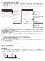
INPUT CONFIGURATION
The IN1 and IN2 are configured separately. In ROB-21, inputs are connected to limit switches that
indicate the position of the gate.
Assigned output
- the parameter defines to which channel a given input (limit switch) is assigned:
• Channel 1 or Channel 2.
Limit switch function
– this parameter defines the function of the limit switch connected to the
given input:
• Closing – limit switch signals closing of gate / pedestrian gate
• Opening – limit switch signals opening of gate / pedestrian gate
• None – limit switch not connected
Limit switch type
– this parameter defines the type of limit switch connected to the given input:
• NO – NO limit switch
• NC – NC limit switch
Press the SAVE button to save the settings.
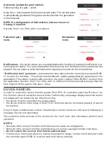
MODE CONFIGURATION
Each ROB-21 channel can operate in one of the following modes:
Gate mode
In this mode, when a remote control button or application button is pressed, a pulse of the dura-
tion specified by “Pulse time” parameter is generated. The mode is used to open/close the gate
– pulses local input at the gate controller.
Pulse duration: 0,1 ÷ 300 s


