background image

13

The specifications of any product may change without prior notice to improve performance. 

Z-MACHINE GT1000

English

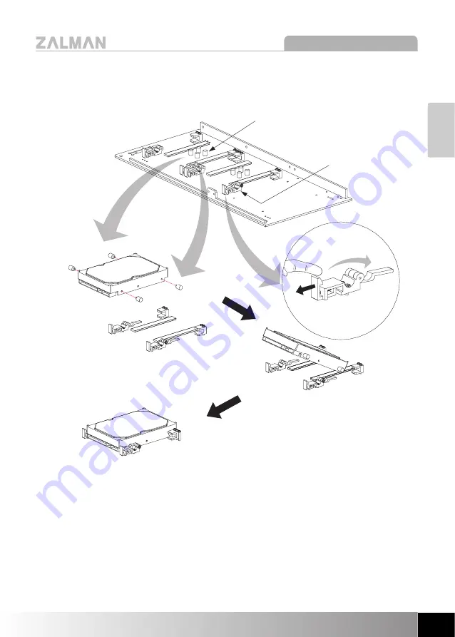
3) HDD Installation & Removal on the Bottom Panel

Remove the AVM(Anti Vibration Mount) installed on the Bottom Panel of the

enclosure and install them on the left/right sides of the HDD. 

Check for an available slot on the Bottom Panel, open the AVM Clamps, and

insert the HDD by gently pushing it.   

Once the HDD is completely lodged in place, close the lever to lock the HDD
in place. 

Note)

Excessive pressure may damage the HDD Lock Bars. Please take cautionary

measures during HDD installation and removal. 

AVM(Anti Vibration Mount)

AVM Clamp

Summary of Contents for Z-MACHINE GT1000

Page 1: ...this manual thoroughly before installation Visit our website and view the Z MACHINE GT1000 installation video first to ease the installation process www zalman co kr www zalmanusa com English version...

Page 2: ...he specifications of any product may change without prior notice to improve performance Table of Contents 1 Safety Notices 3 2 Components 4 3 Specifications 6 4 Front Panel Buttons and I O Ports 7 5 I...

Page 3: ...an lead to fire resulting from short circuit 4 The vents on the front and rear panels must not be blocked 5 Keep this unit away from heat sources and direct sunlight as well as from water oil and humi...

Page 4: ...4 Z MACHINE GT1000 The specifications of any product may change without prior notice to improve performance 2 Components 1 Z MACHINE GT1000 Main Chassis...

Page 5: ...Spare Allen Bolts for enclosure maintenance For motherboard microATX installation For PSU installation For use with GT1000 only For ODD motherboard installation For FDD installation For Fan RPM adjus...

Page 6: ...SU U C Co om mp pa at ti ib bi il li it ty y Standard ATX ATX12V P PC CI I A AG GP P C Ca ar rd d C Co om mp pa at ti ib bi il li it ty y Full Size D Dr ri iv ve e B Ba ay ys s 3 5 Bay 7 T To oo ol l...

Page 7: ...change without prior notice to improve performance Z MACHINE GT1000 English 4 Front Panel Buttons and I O Ports System Power Button System Power LED System HDD Power LEDs 1 2 System Reset Button Audi...

Page 8: ...rove performance 5 Installation Guide 1 Enclosure Disassembly Unscrew the four Bolts Bolt FH M3x6 as shown in the diagram to open the Doors 2 Power Supply Installation Place the PSU on the Power Brack...

Page 9: ...to the enclosure Now install the computer components CPU VGA RAM etc onto the motherboard To install a microATX motherboard first install the 2 enclosed microATX Stand Offs to align the height with th...

Page 10: ...ance 4 5 25 3 5 Drive Installation 1 Remove the Bay Covers of the 5 25 ODD and 3 5 FDD bays 2 Insert the ODD into a bay and fix it in place with the Tool Free Bolts ODD Solts No 3 4 and the FDD Slot a...

Page 11: ...DD Lock Bar of the HDD Chassis Bay where the HDD will be installed Slide in the HDD into the Bay and close lower the HDD Lock Bar behind the HDD To remove the HDD open roll up the HDD Lock Bar above t...

Page 12: ...Pressing the HDD slightly into the HDD Chassis with one hand while rotating the HDD Lock Bar with the other allows easy alignment of the Lock Groove and Tool Free Fixing Screw Hole Align the Lock Groo...

Page 13: ...Panel of the enclosure and install them on the left right sides of the HDD Check for an available slot on the Bottom Panel open the AVM Clamps and insert the HDD by gently pushing it Once the HDD is...

Page 14: ...uct may change without prior notice to improve performance 6 Cable Connection 1 Button PCB Connection Improper connection of the Power LED and HDD LED can lead to LED malfunction Please refer to the m...

Page 15: ...e USB 2 0 IEEE1394a and audio connectors Do not connect the USB2 0 connector to the IEEE1394a connector It will cause serious damage to the product Do not connect the IEEE1394a connector to the USB2 0...

Page 16: ......

Reviews: