background image

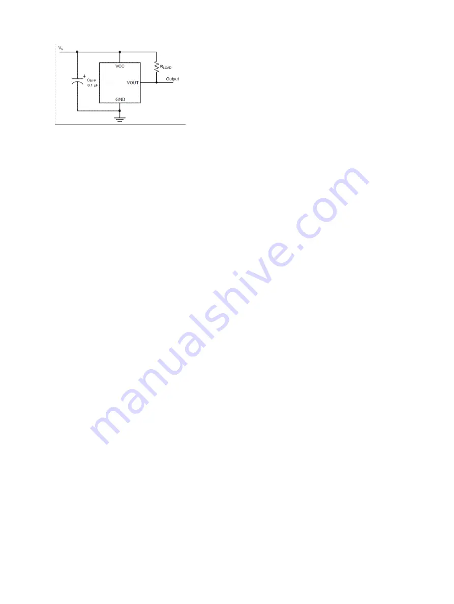
If you are not using a Zaber controller, ensure that your controller has a pull-up resistor on the output line of
the Hall sensor as shown in the diagram. The bypass capacitor is optional, but may help to eliminate false
triggering in noisy environments. The typical value for the pull-up resistor (R

LOAD

) is 10k and for the bypass

capacitor is 0.1uF to 1uF. The larger the capacitance, the better the noise filtering but the slower the response
time.

Home Sensor Wiring

6

Summary of Contents for LSA Series

Page 1: ...roduct User s Manual Firmware 5 00 and up Last Update November 28 2014 Visit www zaber com wiki for more recent updates Zaber Technologies Inc 2 605 West Kent Ave N Vancouver British Columbia Canada V6P 6T7 ...

Page 2: ...15 Connectors A series controllers and peripherals 4 Motor 5 Alternate Controllers 5 Home Sensor Wiring 5 Warranty and Repair 7 Standard products 7 Custom products 7 How to return products 7 Email Updates 8 Contact Information 9 Group Specifications LSA Series 10 Comparison LSA Series 11 i ...

Page 3: ...cal medical aviation or military applications or situations where a product s use or failure could cause personal injury death or damage to property Zaber disclaims any and all liability for injury or other damages resulting from the use of our products Disclaimer 1 ...

Page 4: ...ith care In particular moving parts must be treated with care Avoid axial loads in excess of the rated thrust load axial and radial impact dust and other contaminants and damage to the leadscrew thread These will reduce the performance of the device below stated specifications Precautions 2 ...

Page 5: ...cing Additional M2 threads are also provided on the bottom of the LSA stage for alternate mounting options See the LSA webpage for dimensions resolution and other details LSA stages can be mounted directly in XY using the screws and dowel pins included with the stages They can be mounted in XYZ using our AB106 angle bracket Installation 3 ...

Page 6: ...ore the correct settings for your device send Set Peripheral ID command 66 to the controller with the peripheral ID as the data This ID can also be found on the motor label as ID XXXXX Pinout for D sub 15 Connectors A series controllers and peripherals A series controller female T3 Peripheral male T4 Peripheral male Pin Function 1 5V 2 reserved 3 reserved 4 reserved 5 Home Sensor 6 Ground 7 Motor ...

Page 7: ...ith a hall sensor limit switch The following information is provided for reference only Damage to the actuator or hall sensor due to incorrect wiring is not covered by warranty Home Sensor Wiring A Hall effect sensor is mounted in the device for use as a home sensor It is part number A1122LUA T made by Allegro Click here for data sheet Your controller should be configured so the stage stops immedi...

Page 8: ... shown in the diagram The bypass capacitor is optional but may help to eliminate false triggering in noisy environments The typical value for the pull up resistor RLOAD is 10k and for the bypass capacitor is 0 1uF to 1uF The larger the capacitance the better the noise filtering but the slower the response time Home Sensor Wiring 6 ...

Page 9: ...roducts with faults due to manufacturing defects free of charge Custom products Custom products are any part numbers containing the suffix ENG followed by a 4 digit number Each of these products has been designed for a custom application for a particular customer Custom products are guaranteed for one year unless explicitly stated otherwise During this period Zaber will repair any products with fa...

Page 10: ...ld like to receive our periodic email newsletter including product updates and promotions please sign up online at www zaber com news section Newsletters typically include a promotional offer worth at least 100 Email Updates 8 ...

Page 11: ...methods Phone 1 604 569 3780 direct 1 888 276 8033 toll free in North America Fax 1 604 648 8033 Mail 2 605 West Kent Ave N Vancouver British Columbia Canada V6P 6T7 Web www zaber com Email Please visit our website for up to date email contact information Contact Information 9 ...

Page 12: ...e None Peak Thrust 35 N 7 8 lb Maximum Continuous Thrust 25 N 5 6 lb Guide Type Ball bearing Vertical Runout 4 µm 0 000157 Horizontal Runout 13 µm 0 000512 Linear Motion Per Motor Rev 0 3048 mm 0 012 Motor Steps Per Rev 200 Motor Type Stepper 2 phase Motor Rated Current 240 mA phase Motor Winding Resistance 20 4 ohms phase Inductance 5 mH Motor Rated Power 2 35 Watts Motor Connection D sub 15 Moto...

Page 13: ... unidirectional Maximum Centered Load Maximum Cantilever Load LSA10A T4 10 mm 0 394 18 µm 0 000709 25 N 5 6 lb 100 N cm 141 6 oz in LSA25A T4 25 mm 0 984 24 µm 0 000945 30 N 6 7 lb 125 N cm 177 0 oz in Part Number Pitch Roll Yaw Weight LSA10A T4 0 09 degrees 1 571 mrad 0 03 degrees 0 524 mrad 0 04 degrees 0 698 mrad 0 116 kg LSA25A T4 0 14 degrees 2 443 mrad 0 05 degrees 0 873 mrad 0 12 degrees 2 ...

Reviews: