


CONFIDENTIAL
DOC-USR-0212-01
6
____________________________________________________________________________________
Z3 Technology, LLC
♦
100 N. 8th St. STE 250
♦
Lincoln, NE 68508-1369 USA
♦
+1.402.323.0702
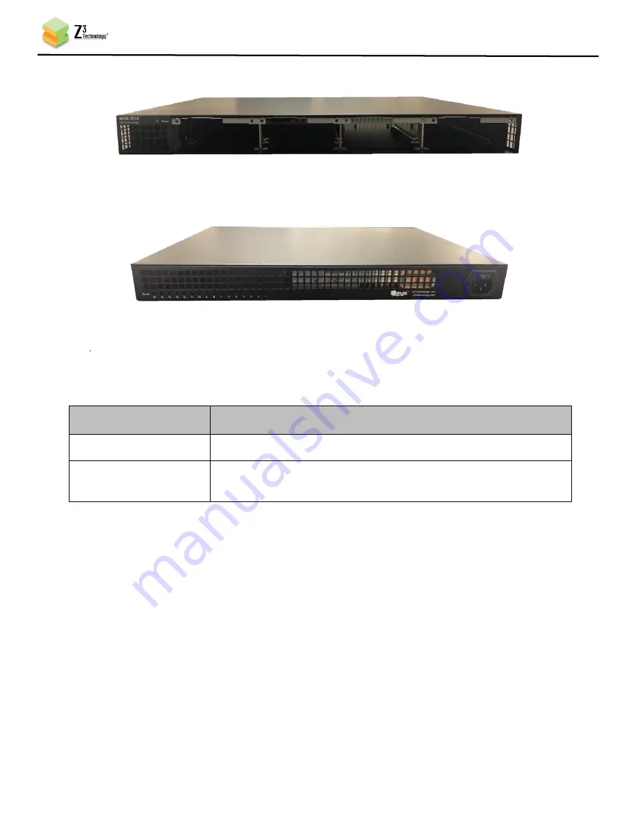
4.1.1
Front View
Figure 2 MVE-R16 Front View
4.1.2
Rear View
Figure 3 MVE-R16 Rear View
4.1.3
LED Indicators
The Power Indicator LED provides a visual indication of the operation status of the chassis as a whole.
The Chassis Power LED indications are:
Power LED
Status
Power LED Green
Power On, chassis
Power LED Red or blink
Red
Alarm triggered by a function on a blade or blade/function locator
request.
Figure 4 Power LED definitions
5.0
CONNECTIONS
All connections to the MVE-R16 frame are on the rear as follows:
5.1
AC Power
Power jack for AC power input, compliant with IEC 60320-1 C14
5.2
Serial Port Jacks
The rear panel contains 16 jacks for serial communications with the functions on the four blades,
divided in four groups of four. Serial jacks number 1 thru 4 are routed to slot 1, serial jacks 5 thru 8
are routed to slot 2 and so on.


