


5
4 By button 4 or double clicks of buttons 3 and 4 (max 8 nodes)
The IP gateway that will receive the scene
activation commands must be placed on all
association groups.
Set and unset associations to actuators
Associations can be assigned and removed either via Z-
Wave commands or using the device itself.
To control a Z-Wave device from the Key Fob, the Node
id of this device needs to be assigned to one of the four
association groups. This is a three-step process:
1. Turn the Key Fob into management mode and hit
button 4 within 10 sec. (LED is blinking green when
management mode is reached).
2. Within 10 sec. push the button of the Key Fob you
like the Z-Wave actuator to be controlled with. After
10 sec. the devices goes back to sleep.
Single click
means adding to this association group, double
click means removing the node selected
in step
(3) from this association group.
3. Find the Z-Wave actuator you like to control by the
device. Hit the button on the device to issue a Node
Information Frame within 20 sec. A common way is
hitting a control button one or three times. Please
consult the manual of the device to be controlled for
more information how to issue a Node Information
Frame. Any button press on Key Fob at this stage will
terminate the process.
Configuration Parameters
Z-Wave products are supposed to work out of the
box after inclusion, however certain configuration
can adapt the function better to user needs or
unlock further enhanced features.
Pair Mode for Button 1 and 3
(Parameter Number 1)
Pair Mode for Button 2 and 4
(Parameter Number 2)
Value Description
0
Separately
1
In pair without double clicks (Default)
2
In pair with double clicks
Control Commands on Group 1
(Parameter Number 11)
Control Commands on Group 2
(Parameter Number 12)
Control Commands on Group 3
(Parameter Number 13)
Control Commands on Group 4
(Parameter Number 14)
Value Description
0
Disabled
1
Switch On/Off and Dim (send Basic Set and Multilevel)
(Default)
2
Switch On/Off only (send Basic Set)
3
Switch All
4
Send Scenes
5
Send Preconfigured Scenes
6
Control devices in proximity
Typical click timeout
(Parameter Number 20)
Typical time used to differentiate click, hold and
double click
Value
Description
1 — 100 in 10ms units (Default 50)
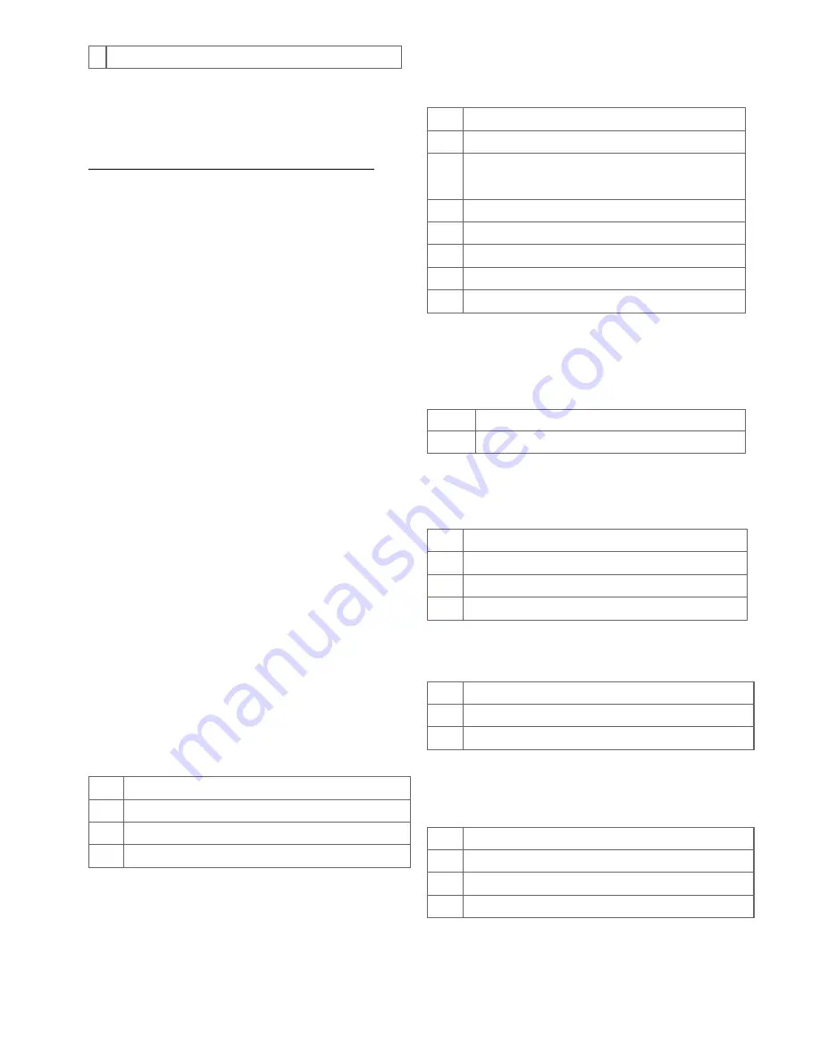
Send the following Switch All commands
(Parameter Number 21)
Value Description
1
Switch off only (Default)
2
Switch on only
255
Switch all on and off
Invert buttons
(Parameter Number 22)
Value Description
0
No (Default)
1
Yes
LED confirmation mode
(Parameter Number 24)
This allows saving battery power
Value Description
0
No confirmations
1
Confirm button press
2
Confirm button press and delivery (Default)
Send unsolicited Battery Report on Wake Up
(Parameter Number 30)


