


2
controller to be included into a Z-Wave network.
The device can be used in different modes that are
selected by configuration parameters:
1. Control of groups of other Z-Wave devices
using ‘ON’, ‘OFF’ and Dim commands.
2. Control of devices in proximity of the FOB
using ‘ALL ON’ or ‘ALL OFF’ commands.
3. Control of a device in proximity of the FOB
using ‘ON’ and ‘OFF’ commands.
4. Activation of predefined scenes in Gateways or
other Z-Wave devices.
Installation Guidelines
The device comes ready to use with a battery
already installed. On factory default the device is
not included in any network and any button push
will result in a long red blink indicating an error.
This behavior can be used to test the factory
default or exclusion state.
For battery change, the device needs to be opened
by removing the three little screws on the backside
of the device. During reassembly, watch the
position of the white rubber and make sure the
silver buttons fit exactly into the nipples of the
rubber.
The device can be operated in two different modes:
•
Operation Mode: This is the mode where the
device is controlling other Z-Wave devices or
is activating scenes.
•
Management Mode: The device is turned into
the management mode by
pushing all four
buttons for 5 sec
. A blinking green LED
indicates the management mode. In the
management mode the buttons of the device
have different functions. If no further action is
performed the device will turn back to the
normal mode after 10 sec. Any management
action terminates the management mode as
well.
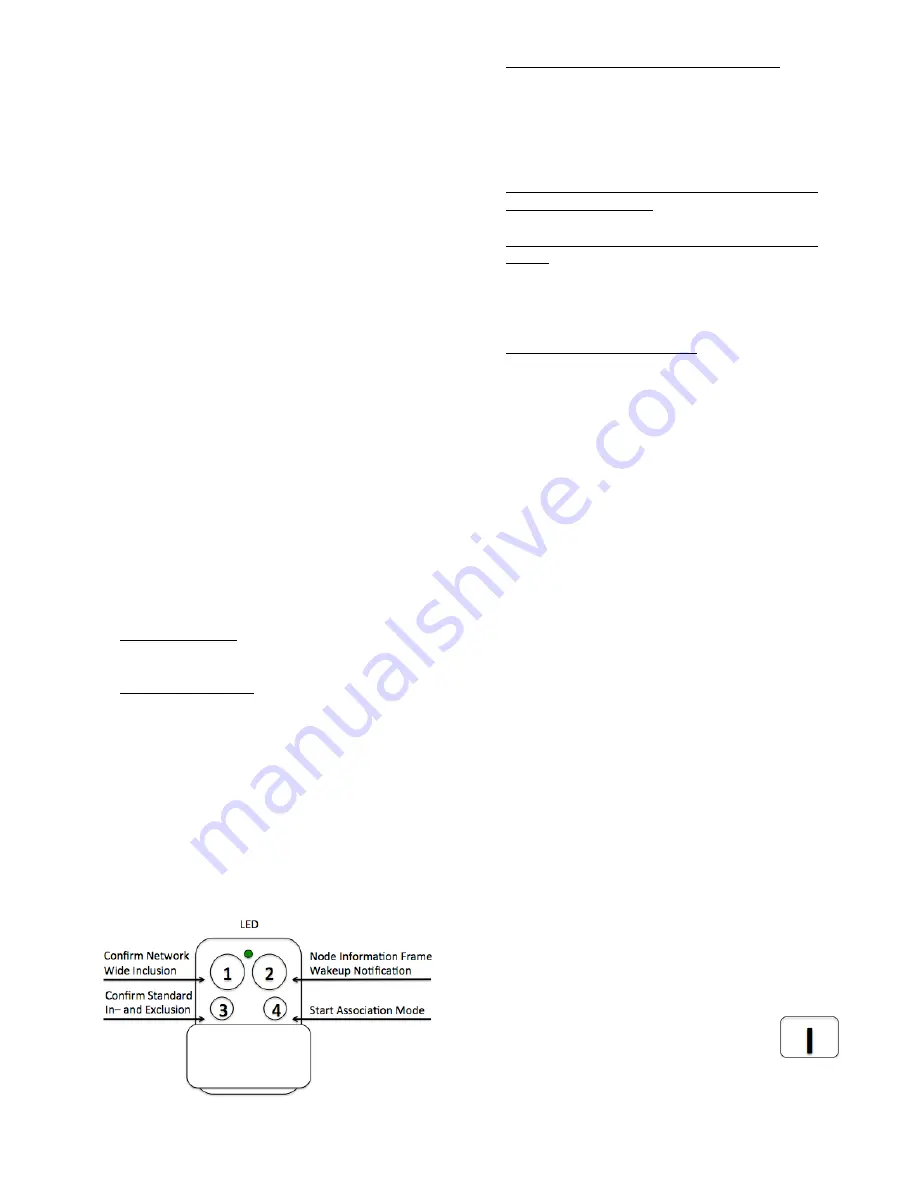
In management mode the following actions can be
performed:
•
Button 1 - Network Wide Inclusion: The
device can be included into a Z-Wave
Network from any physical location in the
network. This requires a primary controller
supporting Explorer Frames. This mode lasts
for 20 seconds and stops automatically. Any
button press stops the mode as well.
•
Button 2 - Send Node Information Frame and
Wake up Notification. (See explanation in the
respective chapters below)
•
Button 3 – Standard Inclusion/Exclusion
Mode: The device is included or excluded
from a controller in direct wireless range. Any
button press stops the mode. Performing an
exclusion of the device from a network resets
the device into its factory default.
•
Button 4 - Association Set: To assign target
devices to one of the four association groups.
Refer to the manuals section about
association for more information how to set
and unset association groups.
Behavior within the Z-Wave network
On factory default, the device does not belong to
any Z-Wave network. The device needs to join an
existing wireless network to communicate with the
devices of this network. This process is
called
Inclusion
. Devices can also leave a
network. This process is called
Exclusion
. The
primary controller of the Z-Wave network initiates
both processes. This controller will be turned into
exclusion respective inclusion mode. Please refer
to your primary controllers manual on how to turn
your controller into inclusion or exclusion mode.
Only if the primary controller is in inclusion or
exclusion mode, this device can join or leave the
network. Leaving the network - i.e. being excluded -
sets the device back to factory default.
Z-Wave knows two types of inclusion processes: The standard
inclusion requires that both controller and the device to be
included are in physical proximity of few meters. The network
wide inclusion allows including a device on every position in
the network as long as there is at least one wireless
connection to a device already included in the network. This
function however requires that both controller and the device to
be included support so-called explorer frames. Please refer to
the technical data of the devices for more information about
explorer frame support.
If the device already belongs to a network, follow
the exclusion process before including it in your
network. Otherwise inclusion of this device will fail.
Once the controller is turned into
standard inclusion mode,
turn the Key
Fob into management mode and hit
Button 3.
Entering management mode and hitting
button 3 when the controller is in exclusion mode


