6
5.1 DynaPak 2010
a. The DynaPak 2010 requires a 3/4" FNPT
pipeline connection.
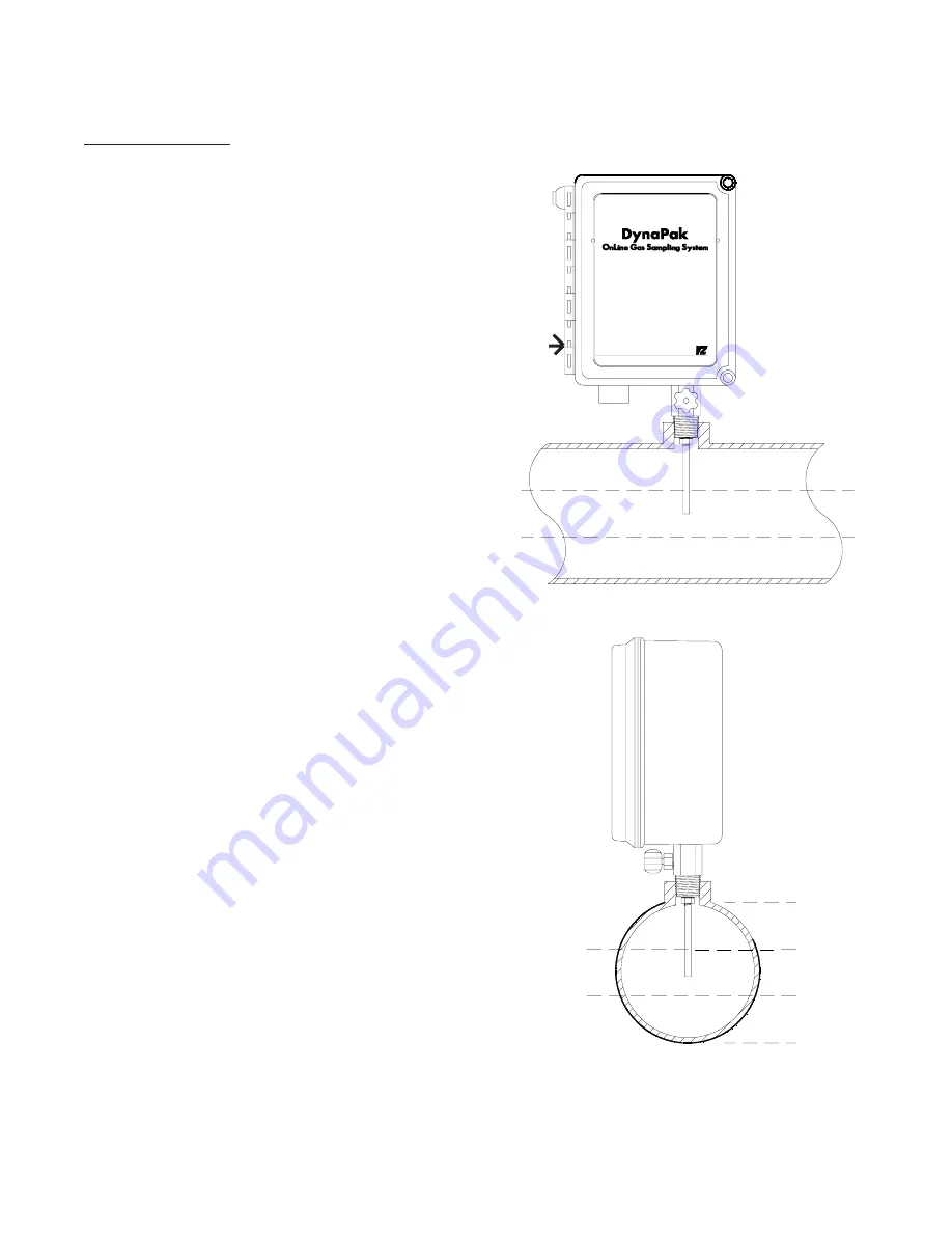
b. The DynaPak 2010 sampler should be
mounted vertically in a horizontal run of the
pipeline.
c. The end of the sampler probe should penetrate
the center 1/3rd of the pipeline.
d. The end of the sample probe should be cut
parallel to the pipeline.
e. Before applying pipeline pressure to the
DynaPak 2010, ensure that the isolation valve and
purge valve are closed.
f. After pipeline pressure has been applied to the
sampler, check the probe body/pipeline connection
using a liquid leak detector.
g. 1/4" stainless steel tubing must be connected
from a source of supply actuation gas with a
minimum pressure of 65 psig to the external gas
supply connection for the Filter Regulator located
on the left side of the sampler enclosure.
CAUTION
Incorrect operation of valves (over tightening) can
result in damage to the valve components (isola-
tion valve bonnet assembly) which might result in
the valve stem being screwed out of the probe
body. This of course results in product at pipeline
pressure being vented continually through this port
until this section of the pipeline is shut in. Be aware
of the following procedures and information.
· DynaPak valves are of soft seat
design and should only be closed
or opened with fingers. No
wrenches should ever be used.
· If a valve will not seal off with
finger tight operation the valve
should have maintenance
performed to allow proper
operation of the valve.
5. System Installation
Center 1/3
1/3
1/3
1/3
Center 1/3
1/3
1/3
1/3
Maximum Pipeline Pressure 1500 psig.
E x t e r n a l
Gas Supply
Connection


