background image

80XX Series H.264 Digital Video Recorder User Manual ………………………………………………….V1.0 

29 


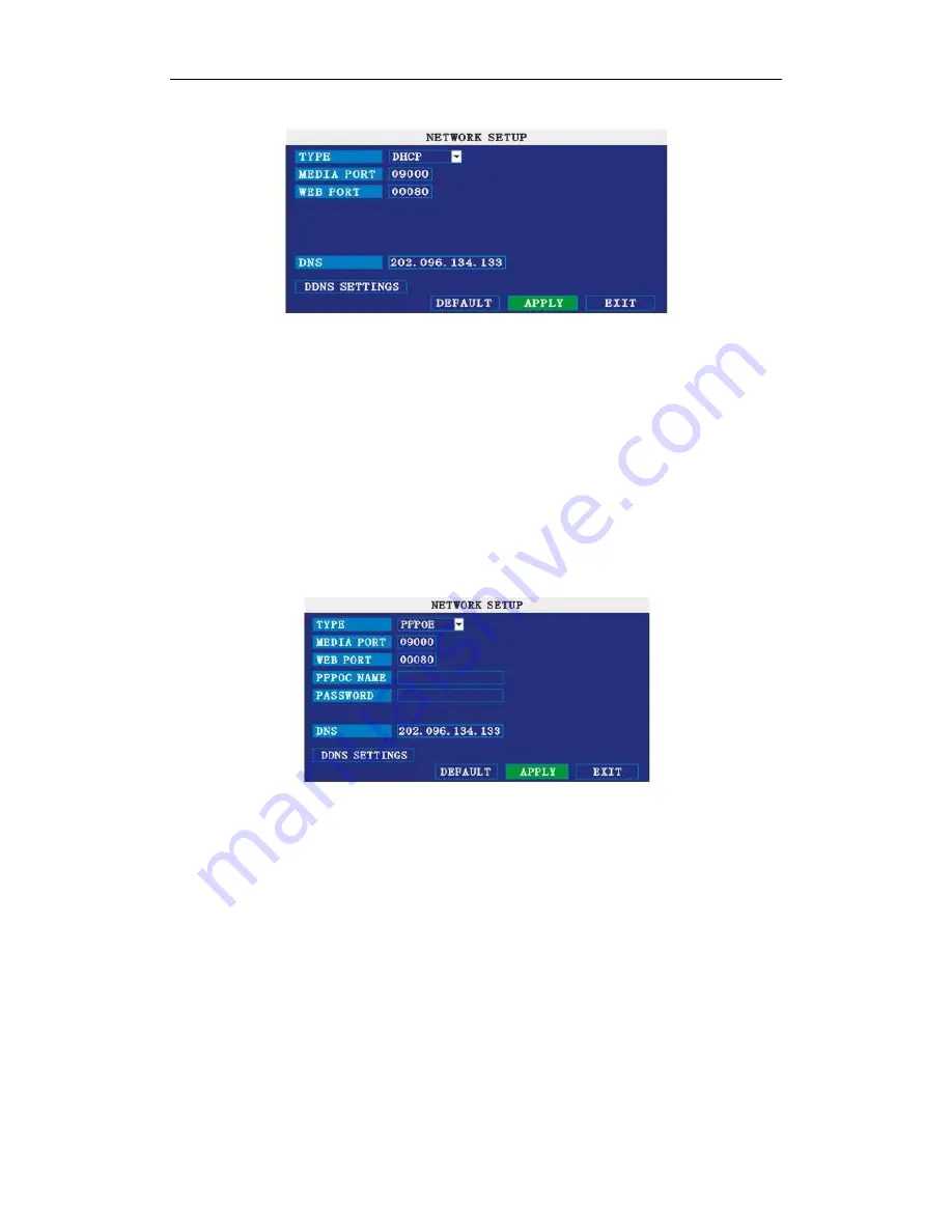
MEDIA PORT: same as static setup 

WEB PORT: same as static setup. 

NOTE: restart system when select DHCP, and it will automatically connect with 

DHCP server. Will allot IP address when connect ok and the address will showed on 

the interface. 

  3 PPPoE   

Select the PPPOE, and enter the interface as followings:   


MEDIA PORT: Port for private protocol of DVR and PC, default : 9000. If this port of 

computer is applied by other server, please change to other free port. 

WEB PORT: Http port. Default: 80. If admin change WEB port to: e.g. 8088, port No. 

should be added behind IP, http://192.168.15.145:8088 should input into IP of IE. 

IP address: Fill in IP address according to the net of DVR; 

Net mask: Fill in net mask according to the net of DVR. 

Gateway: According to the net of DVR, set gateway. If no router of the net, please 

distribute IP address of same web segment; corresponding gateway should set . 

Summary of Contents for 8004

Page 1: ...1 80XX Series H 264 Digital Video Recorder User Manual PLEASE READ CAREFULLY AND SAVE This manual contains important information about this product s operation If you are installing this product for others you must leave this manual or a copy with the end user ...

Page 2: ...80XX Series H 264 Digital Video Recorder User Manual V1 0 2 8004 8004P 8004V 8004VP 8008 8008V 8004TP 8008T 8004AP 8008AV W8004AP W8008AV ...

Page 3: ...80XX Series H 264 Digital Video Recorder User Manual V1 0 3 ...

Page 4: ...ice 9 3 Device operation manual 10 3 1 Remote key instruction 10 3 1 1 Remote control 10 3 1 2 Mouse Operation 11 3 1 3 Menu Configuration 12 3 2 System Operation 13 3 2 1 START UP 13 3 2 2 SYSTEM LOGIN 14 3 2 3GUI OPERATION 14 4 IE OPERATION 34 FEATURE 34 4 2 Restriction condition 34 4 3 User login 34 4 4 OPERATION INTERFACE 35 4 4 1 LIVE 35 4 4 2 PTZ CONTROL 36 4 4 3 ZOOM 36 4 4 4 Focus 36 4 4 5...

Page 5: ...4 16 HOST INFO 41 5 DVR Installation Guideline 42 5 1 Product Overview 42 5 1 1 Product Photo 42 5 1 2 The Definition of Bottoms and Connectors on Front Panel 43 5 1 3 The definition of buttons and connectors on rear panel 44 5 1 4 Connectors for Alarm 45 5 1 5 Alarm Input and Output 45 5 1 6 System Network Diagram 46 5 2 HDD Installation 46 5 3 Wireless Setting 48 6 Device Part 49 6 1 Check Devic...

Page 6: ...e selectable Support mobile surveillance Support network center management system Applied in large surveillance area such as supermarket gas station factory etc 1 3 Parameter 8004Series Model NO 8004 8004V 8004P 8004VP 8004TP 8004AP W8004AP Operation System Embedded Linux Compression H 264 Video Input Output 4 channel BNC input 2 channel BNC output Audio Input Output 4 channel BNC input 1 channel ...

Page 7: ... Fixed TFT VGA Output Yes Software Upgrade USB Mobile Surveillance Support Symbian s60 v3 0 Mobile Pocket PC operation system Digital Wireless Camera No 2 channel Power Supply 19V 2 5A DC 19V 3 42A DC Remote Power Supply No Yes Working Temperature 10 50 Working Humidity 10 90 G W N W 3 3KG 1 7KG 5 3KG 3 7KG 3 7KG 2 2KG Meas L W H 330 230 60mm 330 360 60mm 200 130 230mm 8008 Series Model NO 8008 80...

Page 8: ...larm Input Output 8 channel input 1 channel output Internet IE PPPOE DDNS Remote Control Yes Mouse Control USB USB Port support USB 2 0 PTZ Control Yes Language Support Simplified Chinese English 7 Inch TFT Monitor No Hidden TFT Fixed TFT VGA Output No Yes NO Yes Software Upgrade USB Mobile Surveillance Support Symbian s60 v3 0 Mobile Pocket PC operation system Digital Wireless Camera No 2 channel...

Page 9: ...nd ground Do not touch the power and DVR with a wet hand Do not drop liquid on DVR Do not put others on DVR Please using soft dry cloth when clean DVR do not using chemical solvent When the power line connects with jack even don t startup device There is still have voltage If you do not use device for long time please take the power line away from jack 3 Humidity requirement Please install the dev...

Page 10: ...l keys Move cusor left or right in setup menu QUAD Switch 4 Channels FWD Fast forward the video while playback press PLAY to return to normal speed REV Reverse the video while playback press REW to switch press PLAY to return to normal speed POWER ON Reset the MDVR to Power on and Power off mode standby and start up LOGIN LOCK If the security is enabled in the setup use LOGIN LOCK key to enter the...

Page 11: ...e adjustment color adjustment PTZ setting and VGA border operation It is for setting the single channel for volume adjustment PTZ control and color adjustment If it is multi window please use the left key to select the single window 2 The remark when click the left key for volume adjustment color adjustment VGA border is as follow a There are and for buttons the PTZ setting to adjust parameter cli...

Page 12: ...en check on Pinyin Chinese word 3 When input number click the right key the number soft keyboard will bob up firstly and then use the left key to select the corresponding numerical value Also click the left key to exit the number keyboard Mouse move 1 Press the left key to move the mouse can adjust the parameter on the volume color VGA border interface And the corresponding parameter will be displ...

Page 13: ...n the screen If it has setup ignition recording or time recording the system will record automatically and the corresponding LED will be on and the system work normally Remark 1 If there is no HDD in device or the device didn t read the HDD or the HDD didn t be formatted it will display an H in the video preview interface 2 You must format the HDD in the DVR before first using The steps as follows...

Page 14: ...horities of viewing image searching and play backing video When you input a password the system will automatically match and offer different password with different authorities When DVR started click right key by mouse If you open a password it will enter into user login interface The picture is as follows Ddvice ID You just need to enter the device ID as the right frame Password enter the admin p...

Page 15: ...t the date click search and you can see the recording status on this date Instruction 1 MONTH It will show all the recording status in this month Green means normal recording Red means alarm recording and the default color means no video Click any date in this frame can search the recording status of that day The searching result will be showed in the below date frame 2 DATE It will show all the r...

Page 16: ...n one channel have recording files during selected time will playback all at the same time 3 If let RECORD TIME available in BASIC SETUP it will show the date time when playback record file If RECORD TIME available it will not show the time 4 When playback press SLOW to let the playback slow press FORWARD REVERSE to speed reverse play press PAUSE STEP to pause or playback frame by frame Press Exit...

Page 17: ...g interface As follow showed use direction keys and cursor to change the options CHANNEL ON Means the channel enable for recording RESOLUTION There are HIGHEST HIGH NORMAL three options HIGHEST means the resolution best corresponding to D1 HD1 CIF resolution QUALITY There are BEST FINE and NORMAL three option They are corresponding HIGHEST HIGH and NORMAL data stream standard AUDIO ON Means enable...

Page 18: ...rding during this time Different color means different recording mode Red means alarm recording green means normal recording blue means no recording RECORD SIZE Press Enter or to choose the record size time There are 15min 30min 45min 60min four options that means it will pack as the mode you selected 4 Hard Disk Management Move the cursor to HDD Icon highlighted when selected press Enter to enter...

Page 19: ...ce and press APLLY to format FORMAT Flash Disk Move cursor there to select device and press APLLY to format Note DVR system will restart after HDD formatted but no restart for U Flash disk format 5 BASIC SETUP Move cursor to select BASIC SETUP The big icon means select ok and press ENTER to enter into the system language setup interface Basic setup includes language date time password display and ...

Page 20: ... chose the date DATE FORMAT Press ENTER to switch between the date patterns there are YY MM DD and MM DD YY two options When chose the date format left date will be displayed with corresponding format TIME Press Enter or or press number key to choose the date TIME FORMAT Press ENTER to switch between the date patterns there are 12 HOURS and 24 HOURS two options Left time will be displayed with cor...

Page 21: ... disable enable means user need insert password when log in disable means without password and user can enter into main menu directly USER PASSWORD Press number key to setup ADMIN PASSWORD Press or number key to setup 9 DISPLAY SETUP Move the cursor to BASIC SETUP Icon highlighted when selected press Enter to enter into the setting interface NAME press Enter to enter into the setting interface POS...

Page 22: ...the parameters PREVIEW ON Means the channel is allowed to view the live mode PREVIEW TIME ON Means displaying system date and time above video RECORD TIME ON Means clock will display in the playback of current file 10 VIDEO AUDIO SETUP Move the cursor to VIDEO AUDIO SETUP Icon highlighted when selected press Enter to enter into setting interface 11 ADVANCE SETUP Move the cursor to ADVANCE SETUP Ic...

Page 23: ...s that is when an alarm triggered it will activate the corresponding channel to start alarm recording N O indicate alarm is always OFF it will be ON when have alarm N C indicate alarm is always ON it will be OFF when have alarm HDD LOSS turn on means it will trigger an alarm if there is no HDD and it will display an H On the bottom left of channel 1 in the live view HDD SPACE turn on If the space ...

Page 24: ...cording time setup 30 seconds 1 minute 2 minutes or 5 minutes 13 SYSTEM INFO Move the cursor to SYSTEM INFO frame is red when selected press Enter to enter into system info interface on this interface mainly display system hardware features and firmware version include software version MAC address serial number Picture is below 14 MOTION DETECT Move the cursor to MOTION DETECT Icon highlighted whe...

Page 25: ...ction transparent block means it have not activated motion detection Picture is below Move the direction key on remote control or make cursor move to the need designed area green frame means the cursor has moved to this pane press Enter to select or cancel motion detection of this small pane when setup finished press exit to back to MD setup interface it will save automatically Remark IR Operation...

Page 26: ...Detail setting up please refer to appurtenance 16 SYSTEM PROJECT Move the cursor to SYSTEM PROJECT Frame turns red means selected and press Enter to enter into system project setup interface Picture is below AUTO RESET When switch is on you can setup the time for device to restart SYSTEM UPDATE Copy the update file to the root directory of the flash disk and insert it into USB groove then press En...

Page 27: ...irection key or move cursor to the option and press Enter to switch different channels CHANNEL The channel of PTZ connected PROTOCOL select the protocol of different PTZ there are two protocols to switch and the default is Pelco D BAUD RATE select the different baud rate for your PTZ there are 1200 2400 4800 and 9600 DATA BIT there are 5 6 7 8 options to select default setting is 8 STOP BIT 1 and ...

Page 28: ...tatic Select Static in the CONNECT NETWORK TYPE and press Enter to enter into the interface as followings MEDIA PORT transfers video data between client and device WEB PORT setup the port of IE browser via HTTP IP ADDRESS setup the IP address and press Enter or input numbers to fill IP address NETMASK press Enter or input numbers to fill netmask GATEWAY press Enter or input numbers to fill default...

Page 29: ...A PORT Port for private protocol of DVR and PC default 9000 If this port of computer is applied by other server please change to other free port WEB PORT Http port Default 80 If admin change WEB port to e g 8088 port No should be added behind IP http 192 168 15 145 8088 should input into IP of IE IP address Fill in IP address according to the net of DVR Net mask Fill in net mask according to the n...

Page 30: ... you just register 3 Then please login http members dyndns org with the new user and password click domain name management to enter into the operating interface then select new under the Dynamic DDNS 4 Create a domain name you need then press to apply now you have registered a host name success 20 DVR group network This chapter mainly narrates some networks setting method for your reference 1 Appl...

Page 31: ...ettings is ok 9 Open IE browser and type in the domain name of DDNS if WEB port is not 80 you should add a port please refer to IE setup 10 Please download the IE control then enter into login interface the default setting has no password Press enter and into the preview interface and do what you want according to your need 2 Applied ADSL many types of equipment should share and connect with inter...

Page 32: ...Add DVR s media port and WEB port 9 Use internet remote PC Check if DDNS is successful via ping xxx xxx xxx DVR s domain name 10 Input DDNS into IE address if the WEB port is not 80 port number should add Please refer to IE operation chapter 11 After downloading IE active tool successfully login the interface default is no password press OK to enter preview interface and have your following operat...

Page 33: ...ay etc 4 Net admin add DVR port transfer or sending relation in router 5 Use a computer of LAN input IP of LAN and port number into IE address column to visit the DVR 6 Use internet remote computer input IP and port number of router to IE address column to visit DVR you can start DDNS function After finishing DDNS register and setting users can visit via DDNS and port number This can avoid remembe...

Page 34: ...e visiting of DVR recommend Windows XP Windows Vista operation system recommend browser as IE 6 0 IE 7 0 4 3 User login Input the DVR local IP in IE browser if the web port number is set as 80 directly input IP address into IE address column If not 80 port number should add behind IP E g when IP is 192 168 0 102 set port is 8088 http 192 168 0 102 8088 should input When the net is connected IE wil...

Page 35: ... change the unit No and default password in time for system security NETWORK LAN WAN according to the net type of your computer and DVR Click Login to enter IE interface If input is wrong click Reset to delete and rein put 4 4 OPERATION INTERFACE There are Live view Playback and Setup options in the main interface please press them to access it 4 4 1 LIVE Click to enter into the interface as follo...

Page 36: ...ick to zoom in and out 4 4 4 Focus Click to focus 4 4 5 Iris Click to change the size of aperture 4 4 6 PTZ PRESET Setup preset point You can control it via the below three buttons 4 4 7 PLAY Move cursor to the icons it will highlighted when selected Open all video Capture picture save in local disk system save default route is C DVR Quickly start all channels recording video here the left up corn...

Page 37: ... then click right key will occur window shortcut Menu see below picture You can open shut down and start this channel s record via shortcut menu 3 Click right key at one live view screen click open all windows or close all windows will quickly open close all windows 4 4 9 REPALY Click REPLAY to enter into playback interface Click right up of calendar interface and to setup the month for searching ...

Page 38: ... 5th 6th 8th 9th 10th 11th 12th 17th 18th have recording video and system date is 18th Dec 2008 currently search date is 17th Dec At the below of calendar select channel and type click SEARCH the result will display as follow Double click one item of listed recording video the recording video will playback meanwhile the file icon will change to and will occur the below picture play buttons The abo...

Page 39: ...ick to setup the directory for saving avi file After setting click file convert start the convert progress bar see below picture will see the progress of convert 4 4 10 SETUP Click SETUP to enter into setup interface this interface include record alarm PTZ network setting and system information six menus 4 4 11 RECORD Click RECORD to enter into setup interface you can check the parameter settings ...

Page 40: ...er User Manual V1 0 40 4 4 13 PTZ Click PTZ to enter into setup interface you can check the parameter settings as in GUI of DVR 4 4 14 NETWORK Click NETWORK to enter into setup interface you can check the parameter settings as in GUI of DVR ...

Page 41: ...llocate for traffic that matches internet this bandwidth depends on the place normally around 256 or 384 kbps FILE SAVE PATH capture picture and recording video save path IE login password and DST settings you can check as DVR setting 4 4 16 HOST INFO Click HOST INFO to enter into system information interface see below picture this interface shows HDD status remain record time firmware version MAC...

Page 42: ...X Series H 264 Digital Video Recorder User Manual V1 0 42 5 DVR Installation Guideline 5 1 Product Overview 5 1 1 Product Photo 8004 8004P 8004V 8004VP 8008 8008V 8004TP 8008T 8004AP 8008AV W8004AP W8008AV ...

Page 43: ...r to setup and control PTZ OK PTZ OK PTZ Confirm operation or into PTZ control panel under live view Stop key Stop button Speed choice fast forward button fast reverse button Pause key pause key Single image CH1 CH2 CH3 CH4 single image choice playback PLAY recording playback button MENU EXIT Enter into main menu under live view or exit sub menu HDD HDD Status Control button POW power IR receiver ...

Page 44: ...V or monitor BNC 4 Video input For connecting analog video signal input BNC 5 Audio Input For connecting audio signal Alarm Input I O alarm input 4 for 4CH DVR and 8 for 8CH DVR Alarm Output I O output for alarm RS485 RS 485 for connecting PTZ RS232 For connecting PC 6 12V Power supply for DC relay and the current is 100MA make sure short circuit can not happen 7 Network For connecting Ethernet 8 ...

Page 45: ...maintained and change new one if the fan has some problems 5 1 4 Connectors for Alarm Peel off the color skin of the cable and then insert the cable into the slot on the rear panel DVR 5 1 5 Alarm Input and Output There are 8 sets alarm input connector and 1 set output for this DVR Alarm input is for connection IR annunciation fog sensor The connection diagram of DC alarm inout as following ...

Page 46: ... AC alarm input as following The connection diagram of alarm output as following 5 1 6 System Network Diagram 5 2 HDD Installation Please installation the HDD as the following steps 1 Uninstall the DVR and then you will see one HDD plate as following RELAY 220V AC 12V DVR I O output ...

Page 47: ... V1 0 47 2 Connect HDD line as follows 3 Install the HDD on HDD plate as the following photo indicate and then screws around 4 Fix the HDD plate on the DVR device and then cover the DVR and screw Notice Newly installed HDD should format before recording ...

Page 48: ...80XX Series H 264 Digital Video Recorder User Manual V1 0 48 5 3 Wireless Setting ...

Page 49: ...80XX Series H 264 Digital Video Recorder User Manual V1 0 49 6 Device Part 6 1 Check Device part 1 Digital Video Recorder 1 SET 2 Standard Part 3 Optional Part ...

Page 50: ...track hard drive or the line of hard drive is bad On off power supply is not enough The front end video signal instability High temperature too much dust too bad the DVR operating environment The main board is not well connected with other board The hardware of DVR is fault 3 Question Why there is no output of single channel multi channel or all channel video Answer Please check the adaptor of cam...

Page 51: ...on What is meaning by R M I H showed in interface Answer R means the channel is recording M means the channel is being motion detection I means the channel is being alarm H means there is no HDD the HDD is bad or the space of HDD is full 6 Question Why DVR has the problem of real time image such as video image color serious bright distortion Answer BNC output selectable PAL and NTSC is not correct...

Page 52: ... PTZ Answer The front end PTZ is fault The PTZ decoder setting connecting and installing is not correct The connect is not correct The PTZ setting of DVR is not correct The PTZ decoder does not match with the DVR agreement When connecting multi decoder 120 Ω electric resistances should add at the end of PTZ decoder AB line or else PTZ will not be stable The distance is too far 11 Question Why the ...

Page 53: ...or few moving 100 150 M byte of each channel per hour when video has big moving or much moving 13 Question Why it can t do motion detection Answer The setting of the area of motion detection is not correct Low sensitivity 14 Question CD writer USB backup error Answer The data exceeds the capacity of backup device The backup device is incompatible The backup device is damaged 15 Question Why I O al...

Page 54: ...m using IE6 0 browser or IE7 0 browser ActiveX control is been blocked Please manual install ActiveX control Please install DX8 1 and upgrade your video card driver 18 Question There is no picture or not clear when you preview the recording or playback the recording by IE Answer If you visit DVR by IE please choose Wan in web environment Please try to Close windows by the right mouse button and tr...

Reviews: