background image

6

Unconditioned Spaces

All duct work passing through unconditioned space must 
be properly insulated to minimize duct losses and prevent 
condensation. Use insulation with an outer vapor barrier. 
Refer to local codes for insulation material requirements.

Acoustical Duct Work

• 

Certain installations may require the use of acoustical 
lining inside the supply duct work. Acoustical insulation 
must be in accordance with the current revision of the 
Sheet Metal and Air Conditioning Contractors National 
Association (SMACNA) application standard for duct 
liners. Duct lining must be UL classified batts or blankets 
with a fire hazard classification of FHC-25/50 or less.

•  Fiber duct work may be used in place of internal duct 

liners if the fiber duct work is in accordance with the 
current revision of the SMACNA construction standard 
on fibrous glass ducts. Fibrous duct work and internal 
acoustical lining must be NFPA Class 1 air ducts when 
tested per UL Standard 181 for Class 1 ducts.

• 

Damping ducts, flexible vibration isolators, or pleated 
media-style filters on the return air inlet of the electric 
furnace may be used to reduce the transmission of 
equipment noise eminating from the electric furnace. 
These treatments can produce a quieter installation, 
particularly in the heated space. However, they can 
increase the pressure drop in the duct system. Care 
must be taken to maintain the proper maximum pressure 
rise across the electric furnace, temperature rise and 
flow rate. This may mean increasing the duct size and/
or reducing the blower speed. These treatments must 
be constructed and installed in accordance with NFPA 
and SMACNA construction standards. Consult with 
local codes for special requirements. For best sound 
performance, be sure to install all the needed gaskets 
and grommets around penetrations into the electric 
furnace, such as for electrical wiring.

Air Filters

B5BV series electric furnaces are not supplied with an 
air filter when shipped from the factory. The installer must 
provide a high velocity filter that is appropriately sized 
to the return air duct opening or filter rack located in the 
bottom of the unit. Accessing the filter does not require 
tools and can be removed from the front of the unit by 
removing the filter door. See Unit Maintenance (page 12) 
for filter sizes and installation information.

 WARNING:

Never operate the electric furnace without a 
filter or with doors removed. Dust and lint can 
build up on internal components, resulting 
in loss of efficiency, equipment damage, and 
possible fire.

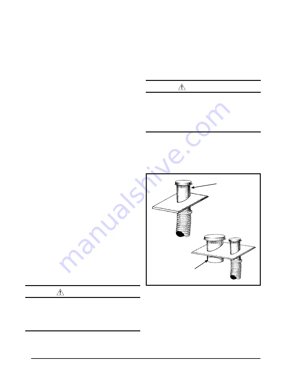
VentilAire III

VentilAire IV

Figure 2. VentilAire III & IV

Ventilaire III or IV Air Quality Package (Accessory)

The B5BV electric furnace has a cutout on each side of 
the cabinet for ventialtion air. The Ventilaire air quality 
packages introduce outdoor air into the living space during 
furnace blower operation. The VentilAire IV also serves to 
exhaust moist and/or hot air from the attic space. These 
packages meet the ventilation requirements as outlined 
in H.U.D. Standard Part 3280.103 (b) (2). See Figure 2 
for typical installation.

 CAUTION:

MAINTAIN 2 1/2” MINIMUM CLEARANCE 
BETWEEN FLUE PIPE AND FLEX DUCT. FAILURE 
TO COMPLY WITh ThIS RESTRICTION COULD 
CAUSE EQUIPMENT DAMAGE. VENTILAIRE III 
ILLUSTRATED OThER LISTED VARIATIONS 
AVAILABLE. ChECK WITh MANUFACTURER.

Use adaptor (part number 914427) with Ventilaire III or 
IV to supply the proper amount of ventilation air. The 
VentilAire connections must be made for the system to 
conform to H.U.D. rules. Do not leave disconnected after 
servicing or adding A/C to the system. Complete installation 
instructions are supplied with each air quality package.

Summary of Contents for B5BV Series

Page 1: ...cial notes highlighted in the manual Improper installation of the furnace or failure to follow safety warnings could result in serious injury death or property damage Please read all instructions care...

Page 2: ...Supply Circuits 10 Control Board 10 Twinning 10 Thermostat Low Voltage Connections 10 Grounding 10 Startup Adjustments 11 Before You Start the Unit 11 Air Circulation Check 11 Running the Blower Conti...

Page 3: ...ctric Code ANSI NFPA 70 For Canadian installations the electrical connectionsandgroundingshallcomplywiththecurrent Canadian Electrical Code CSA C22 1 and or local codes Installationofequipmentmayrequi...

Page 4: ...rant tubing This unit should be located with consideration of minimizing the length of the supply and return ducts Refer to the rating plate or Table 3 page 15 for proper circulating airflow data Figu...

Page 5: ...essure shown on the furnace rating plate The supply air must be delivered to the heated space by duct s secured to the furnace casing running full length and without interruption Circulating Air Suppl...

Page 6: ...r best sound performance be sure to install all the needed gaskets and grommets around penetrations into the electric furnace such as for electrical wiring Air Filters B5BV series electric furnaces ar...

Page 7: ...th sheet metal screws Make sure the screws penetrate the sheet metal casing and flanges Tape or seal all seams if required by local code NOTE If an upflow pedestal mounting stand is fabricated in the...

Page 8: ...nnector and cut out the marked area of the supply air duct NOTE Toallowsomeclearanceforinstallingtheplenum connector cut the opening 1 4 larger the actual cutout drawn 6 Install the duct connector bac...

Page 9: ...lso be installed in a horizontal application with the unit suspended from the ceiling If suspending the electricfurnacefromtheceiling assembleasupportframe using slotted iron channel and full threaded...

Page 10: ...ce controls the timing sequence of the elements The board is equipped with a 3 second blower ON delay and a 15 second blower OFF delay in heating and a 40 second blower OFF delay in cooling Twinning E...

Page 11: ...temperature above room temperature and observe that the blower energizes Checktheairbeingdischargedattheregister is warmer than room temperature 2 Allow the unit to run for several minutes and then se...

Page 12: ...s recommended that the filter be cleaned or replacedmonthly Newlybuiltorrecentlyrenovatedhomes mayrequiremorefrequentchanginguntiltheconstruction dust has minimized Filter sizes shown in Table 2 are a...

Page 13: ...B 19 3 4 18 1 4 49 3 8 C 22 1 2 21 56 3 4 3 4 3 4 13 1 7 8 K O 11 8 K O typ 11 4 15 8 17 8 11 4 3 1 4 2 5 8 11 8 K O typ 13 4 K O typ 1 7 8 3 5 8 5 5 8 DETAIL D 3 1 4 2 1 4 15 1 4 13 SUCTION LIQUID W...

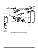
Page 14: ...Transformer Capacitor Circuit Breaker 60A Heating Element Assembly Blower Wheel Blower Housing Motor Control Board Control Board Filter Door Upper Door Assembly Lower Door Assembly Figure 10 B5BV Ser...

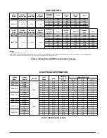
Page 15: ...1576 1783 NOTES 1 Airflow is shown in cfm 5 2 All airflows are measured without filter and with dry coil For filter velocity of 300 ft min subtract 08 external static pressure For wet coil subtract 1...

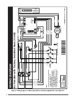
Page 16: ...peed tap connection may not be as shown See the Installation Instructions 2 Disconnect all power before servicing 3 Transformer may have a dual voltage primary tap Match the tap position with the supp...

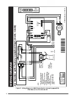
Page 17: ...GREY BLUE ORANGE POWER PLUG LIMIT RED RED RED RED BLACK BLACK RED BLACK RELAY RELAY TERMINAL BLOCK for select models only CIRCUIT BREAKER Circuit breaker models only BLUE W2 W1 O Y Y2 G R C X13 MOTOR...

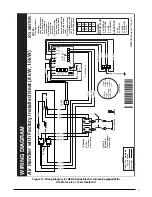
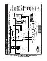
Page 18: ...d 4 If the Internal wiring is replaced use only 105 C copper wire of the same gauge W2 W1 O Y Y2 G R C 4 SPD MOTOR 1 2 3 5 6 4 TRANSFORMER 24V BLACK RED WHITE BLACK WHITE FUSE L2 COM 2 L2 L2 COM L1 VS...

Page 19: ...ANSFORMER 24V BLACK RED WHITE BLACK WHITE FUSE BLOWER MOTOR PLUG C L G N N NEUTRAL G GROUND L LINE C COMMON L2 L2 L2 COM L1 L1 XFMR X13 COOL X13 HEAT 24 VAC RED COM GREY Y1 C L G N WHITE X13 COM RED B...

Page 20: ...h B5 Electric Furnace G R C E O Y Thermostat NOTE Jumper W1 W2 together for shorter staging time W2 W1 O Y G R C W2 W1 O Y G R C NOTE Jumper W1 W2 together for shorter staging time Air Handler W2 O W2...

Page 21: ...21...

Page 22: ...22...

Page 23: ...23...

Page 24: ...at been calibrated YES NO Is the thermostat level YES NO Is the heat anticipator setting correct YES NO VENTING SYSTEM Is there adequate fresh air supply for ventilation YES NO Vent free from restrict...

Reviews: