


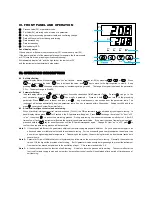


FIL
PV input filter
The value of FIL will determine the ability of filtering noise.
When a large value is set, the measurement input is stabilized but the
response speed is slow. Generally, it can be set to 1 to 3.
If great interference exists, then you can increase parameter “FIL”
gradually to make momentary fluctuation of measured value less than
2 to 5.
When the instrument is being metrological verified, “FIL” s can be set
to 0 or 1 to shorten the response time.
0
~
40
Fru
Selection of
power frequency
and temperature
scale
50C: 50Hz,
℃
50F: 50Hz,
℉
60C: 60Hz,
℃
60F: 60Hz,
℉
SPH
Upper limit of SV
Maximum value that SV allowed to be. When SPH=400, the SV range
will 0~400
℃
0
~
999
℃
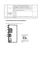
VI.
INSTRUMENT INSTALLATION AND WIRING
Wiring graph for instruments with dimension A, B, E or F
Note: The graph suits for
upright instruments with
dimension A or E
For instruments with
dimension B or F size, just
clockwise rotate the graph
90 degree.
1
2
3
4
5
6
7
8
9
10
100-240VAC~
+
AUX
AU2
AU1
COM
COM
N/O
N/O
N/O
N/C
+
+
Alarm Output
N/O
COM
+
Main Output