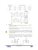
20
YT-1000/1050 series
Actuator stem
height (H)
Markings of bolt holes
A-L
B-L
A-R
B-R
20mm
H : 20
H : 20, 30
H : 20
H : 20, 30
30mm
H : 30
H : 20, 30
H : 30
H : 20, 30
50mm
H : 50
H : 50
H : 50
H : 50
3.3.2
Installation Steps
1. Please check the actuator’s stem height and adjust the bracket by
referring to the bracket table.
2. Attached the bracket onto the actuator. It is recommended to use spring washer so the
bolts will not be loosen from vibration.
3. Set rotation position of the actuator stem at 0%. For single acting actuator, it is easy to
check 0% point by supplying no pressure to the actuator. For double acting actuator,
check actuator stem’s rotation direction – clockwise or counter-clockwise - by supplying
pressure to the actuator.
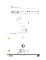
4. Install the fork lever after setting actuator’s stem at 0%. Check the actuator stem’s
rotation direction – clockwise or counter-clockwise. Installation angle of the fork lever
should be 45 degrees in relation to the linear shaft. For NAMUR shaft installation, the
angle does not matter.
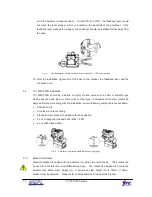
Fig. 6:
Counter-clockwise and clockwise rotation.
Summary of Contents for YT-1000L
Page 1: ...Electro Pneumatic Positioner PRODUCT MANUAL YT 1000 1050 SERIES VERSION 1 01...
Page 7: ...7 YT 1000 1050 series 2 4 2 YT 1000R...
Page 8: ...8 YT 1000 1050 series 2 4 3 YT 1050...
Page 11: ...11 YT 1000 1050 series 2 6 Parts and Assembly 2 6 1 YT 1000 1050L 2 6 2 YT 1000 1050R...
Page 12: ...12 YT 1000 1050 series 2 6 3 YT 1000L SPTM Internal 2 6 4 YT 1000R SPTM Internal...
Page 13: ...13 YT 1000 1050 series 2 6 5 YT 1000R L S Internal 2 6 6 YT 10000R SPTM L S Internal...
Page 16: ...16 YT 1000 1050 series 2 7 8 YT 1050L 2 7 9 YT 1050R...


