YSI 650 MDS Operation Manual Download Page 41

YSI Incorporated

41

650 MDS

Note that Site lists containing

 Single


Site 

Designations are usually input with the designation

 Store Site

Number 

INACTIVE in the

 650


Logging setup

 menu.  Thus, no site numbers appear in the first 

Site list

example.  Conversely, 

Site lists

 containing 

Multi-Site Designations

 MUST be input with the 

Store Site

Number

 selection ACTIVE as shown in the second example.

As noted above, establishment of either of these two types of 

Site Designations

 that are stored in 650

memory in a 

Site List

 will allow you to log field data to the 650 memory without entering file/site

information from the 650 keypad in the field at each site.  You will easily be able to access previously
entered 

Site Designation

 information from this the 

Site List

 at each field site and thus simplify your record

keeping and logging procedures.   To utilize the full capability of the 650 logging system, you will need to
understand how to set up and use these two types of 

Site Designations

, particularly if you are performing

multiple or replicate logging studies at various field sites.  The following discussion and examples should
help you understand how to set up site lists for various applications.

LOGGING OF DATA TO 650 MEMORY FROM SINGLE SITES TO SINGLE FILES – USE OF
SINGLE-SITE DESIGNATIONS IN A SITE LIST

The setup and use of 

Single-Site Designations

 will be provided in the following application example:

Water quality data needs to be collected for two sites at the West and East ends of a lake (Blue Lake) at
various time intervals for 30 days.  The environmental scientists want all of the data for each site to be in a
separate data file that can be reported from EcoWatch for Windows or from a spreadsheet.  The key to this
application is that each physical location will need to be characterized by a different 

File Name

 in the 

Site

Designation

.

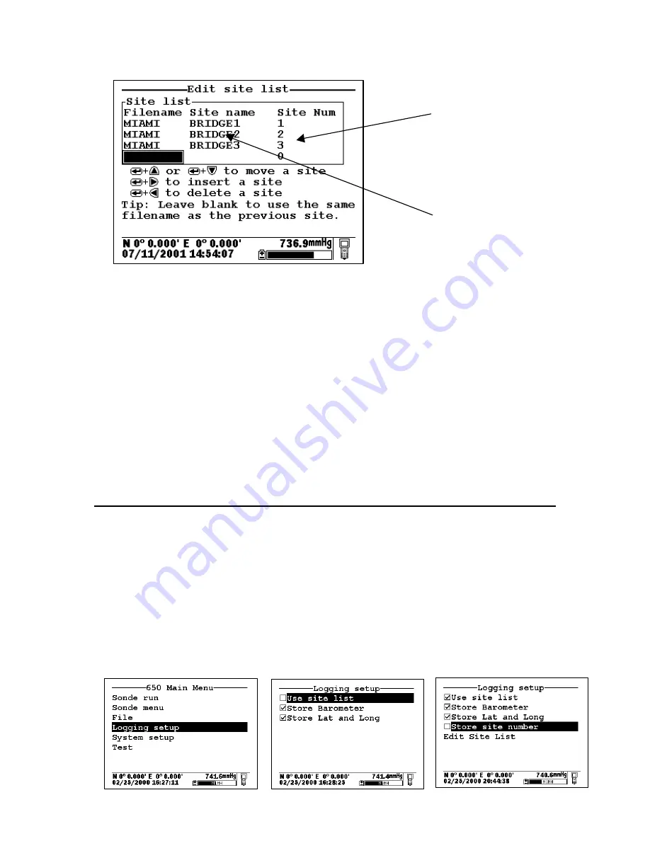
To establish a site list in the 650 memory for this application, highlight the 

Logging setup

 selection in the

650 Main menu and press 

Enter

.  The following screen will appear.  Make certain that the selection 

Use

Site list

 is active to display the full capability of the Logging setup as shown below.   To set up a list with

Single-Site Designations the selection 

Store Site number

 should be INACTIVE (as shown below) before

proceeding.

Site List

Multi-Site Designations with
the Same File Name

Summary of Contents for 650 MDS

Page 1: ...P u r e D a t a f o r a H e a l t h y P l a n e t YSI 650 MDS Multiparameter Display System Operations Manual YSI Environmental ...

Page 2: ...YSI Incorporated 2 650 MDS ...

Page 3: ...OGGING 31 5 2 LOGGING DATA TO SONDE MEMORY 33 5 3 LOGGING DATA TO 650 MEMORY 37 5 4 650 LOGGING CANS AND CAN TS 48 SECTION 6 MANAGING 650 FILES 50 6 1 INTRODUCTION 50 6 2 DIRECTORY 51 6 3 UPLOAD TO PC 52 6 4 VIEW FILE 53 6 5 FILE MEMORY 54 6 6 DELETE ALL FILES 54 SECTION 7 UPLOADING DATA FROM SONDES 55 7 1 INTRODUCTION 55 7 2 UPLOAD PROCEDURE 55 SECTION 8 USING GPS WITH THE 650 55 8 1 SETTING UP T...

Page 4: ...ble to locate the Declaration of Conformity that was shipped with your instrument contact your local YSI representative or YSI Customer Service in Yellow Springs Ohio for a copy of the document See Section 14 Warranty and Service Information for contact information In addition if you are using your 650 in a European Community CE country Australia or New Zealand you MUST install a clamp on ferrite ...

Page 5: ... the user to easily Display real time readings from YSI 6 series sondes Log real time sonde data to internal meter memory with custom site lists Calibrate 6 series sondes Set up 6 series sondes for deployment Upload data from sondes for transfer to PC SECTION 2 GETTING STARTED This section is designed to quickly familiarize you with the hardware and software components of the YSI 650 and its acces...

Page 6: ...le Battery Pack Kit with 6116 charger adapter cable 6123 universal charger China Australia power cord and 6117 battery pack included 4654 Tripod 614 Ultra Clamp 5085 Hands Free Harness 5065 Form fitting Case 5081 Hard sided Case 6117 Extra Rechargeable Battery Pack 6115 GPS Cable for interface with user supplied GPS unit 616 Cigarette Lighter Charger If you have ordered any of these accessories wi...

Page 7: ...T is uploaded initially with a memory allocation of 50 kB and then is uploaded at a later time and overwritten with a memory allocation of 100 kB the total memory occupied is 150 KB even though only one file with the designation TEST and a file size of 100 kB is shown in the file directory For this reason when dealing with large files the user may wish to transfer files to a PC immediately after u...

Page 8: ... upgrade You will need 650 6115 GPS cable User supplied GPS unit with DE 9 cable YSI 6 series sonde with integral or field cable 650 YSI 6 series sonde Integral or field cable User supplied GPS unit with DE 9 cable 6115 GPS cable You will need 650 YSI 655174 PC interface cable PC with active serial port 650 PC Serial port DE 9 655174 PC Interface Cable ...

Page 9: ...subsequent sections of this manual They are presented here so that your will be able to ascertain if you have all of the parts necessary for your applications You will need 650 with battery pack installed 6116 Charger adapter cable 6114 Wall charger or equivalent 6116 Charger adapter cable 6114 wall charger shown or 6123 power supply 650 ...

Page 10: ...above There are four function keys up down right and left arrow keys and an alpha numeric keypad The top left key that has a green circle and line is the ON OFF key The top right key activates the display backlight The Escape key is labeled and is the Enter key Display Backlight Key On Off Key Cellular Phone Style Keypad Enter Key Escape Key MS 8 Connector Strain Relief Lanyard 650 Front View Arro...

Page 11: ...to the strain relief of the sonde cable Simply open the D ring pass the lanyard loop through the opening and then close the D ring 2 5 BATTERIES AND CHARGING The YSI 650 can be powered either with 4 alkaline C cells or a rechargeable NiMH battery pack With the C cell configuration the user will be able to power a typical YSI 6 series sonde active dissolved oxygen and one optical sensor for approxi...

Page 12: ...lation Reinstall battery lid and tighten the 4 captive screws securely and evenly using a Phillips or slotted screwdriver Do not overtighten 2 5 2 BATTERY INSTALLATION RECHARGEABLE BATTERY PACK The YSI 6113 rechargeable battery pack is self contained and is easily installed according to the instructions and diagrams below Using a Phillips or slotted screwdriver loosen the 4 captive screws on the b...

Page 13: ...rage keep your battery pack between the temperatures of 20 C and 30 C and remove it from the 650 case 5 Do not charge your batteries at temperatures below 0 C or above 40 C 6 Do not use or store the battery pack at high temperature such as in strong direct sunlight in cars during hot weather or directly in front of heaters If the above steps are not followed it may result in a decrease in the oper...

Page 14: ... The 616 cigarette lighter charger contains a 2 ampere fast blow type fuse If the power cord stops working properly unscrew the adapter s cap remove the tip and then pull out and check the fuse See diagram above to remove the fuse If the fuse is blown or you are unsure replace it with a new 2 amp fast blow fuse that is available at electronics stores such as Radio Shack Reassemble the adapter and ...

Page 15: ...p right of the keypad The instrument backlight should illuminate the LCD so that the display can be read Pushing the backlight key again will turn the backlight off The backlight will power off automatically after two minutes of non use 2 7 ADJUSTING THE DISPLAY CONTRAST The contrast of the 650 display is automatically temperature compensated to provide a proper display under most field conditions...

Page 16: ...changing entries such as DO warm up time and optical wiper interval in the Sonde Advanced Sensor submenu You will follow an example of this type of entry when you set the 650 clock in the example below When both numeric and alpha entry are appropriate for input the 650 keypad provides a cellular phone style interface for choosing the proper character As shown in the above diagram the 2 9 keys can ...

Page 17: ...ght to prepare for the next alphanumeric input If you make a mistake in the entry simply return to the previous character with the left arrow key and reenter the number or letter After the entry is complete press the Enter key to confirm it You will follow an example of this type of entry when you enter an Instrument ID name for your 650 in the example below To familiarize yourself with the basics...

Page 18: ...r the proper number from the keypad for the first date digit Note that when you release the key the cursor moves automatically to the next number Repeat this process until the date is correct Then press Enter to confirm the Date entry Note also that as described above since alpha characters are inappropriate for this entry only numeric entry is possible Highlight the Time selection and press Enter...

Page 19: ...ber 2 as opposed to the previous clock setting example where a single press of the numeric 2 key generated the number 2 After completing the above example press the Escape key repeatedly to return to the 650 Main menu and then proceed to the next section 2 9 CONNECTING TO A SONDE The primary use of the 650 is to interface with YSI 6 series sondes In this configuration you will be able to see data ...

Page 20: ...f this manual Note also that there is a disk with rotating segments in the upper right corner of the display whose movement confirms that the 650 sonde interface is functional To return to the 650 Main menu press the Escape key CAUTION When using the 650 MDS in field applications which are in close proximity to communication towers and heavy industrial equipment or which involve very low humidity ...

Page 21: ... used in calibration of sonde dissolved oxygen sensors The barometer reading is NOT corrected to sea level and is updated in real time 2 10 4 Battery Capacity Status The graphic indicator shows the portion of the battery capacity that is remaining either for the 4 C cell configuration or for the optional rechargeable battery pack If a 6117 rechargeable battery pack is in place a NiMH label will ap...

Page 22: ...act YSI Customer Service for advice After reading the above sections and participating in the simple examples provided you should be familiar with the basics of battery installation keypad and display function and keypad data entry Please proceed to Section 3 where the setup of your 650 is described in detail SECTION 3 SETTING UP THE 650 The 650 has a number of features which are user selectable o...

Page 23: ...ries by deactivating this selection Note that the selection MUST BE OFF in order to determine the voltage of the internal batteries of sondes important information for Unattended studies 3 4 Baud rate to sonde This entry allows the user to adjust the baud rate for communication with the sonde It does not affect communication for upload of files to a PC Highlight the entry and press Enter Then sele...

Page 24: ... pressure value from your local weather service This latter value has usually been corrected to sea level and therefore must be uncorrected before it can be used in calibration of the 650 barometer See Section 9 of this manual for details Select Calibrate barometer and press Enter Input the known barometric pressure from the 650 keypad in the selected units mm Hg in the following example and press...

Page 25: ...ssible if the sonde were attached to a PC From the 650 Main Menu select Sonde menu and press Enter A display similar depending on sonde type and sonde software version to that shown below will appear Note that the icon in the lower right of the screen has changed from meter to sonde indicating that the menu shown originates in the 6 series sonde Note also that the 650 display has been designed to ...

Page 26: ...s Setting up the desired Report output Calibrating the sensors Changing the sample interval for Discrete Sample studies Performing file management functions on the memory in the sonde Checking the Status or System setupof the sonde Setting up sondes for Unattendedsample deployments Setting up sondes for Discrete sample logging studies to sonde memory Uploading files from the sonde memory to the 65...

Page 27: ...the highlighting block down with the arrow key After activation of salinity in the Report setup of the sonde press the Escape key twice in succession to return to the Main sonde menu Example 2 Calibrating the Dissolved Oxygen Sensor NOTE In the following example it is assumed that the Autosleep RS232 function of your sonde has been disabled in the sonde Advanced Setup menu If Autosleep were active...

Page 28: ... the Enter key and observe the dissolved oxygen reading until stabilization occurs Make sure the Calibrate selection is highlighted in upper window NOTE The current barometric pressure as read by your 650 will automatically appear as the default value if your 650 is equipped with a barometer When the dissolved oxygen reading is stable press the Enter key to confirm the calibration as indicated by ...

Page 29: ...t to higher values in the Discrete Sample menu This feature will be described in detail in Section 5 To Run the sonde from the Discrete sample menu highlight Start sampling and press the Enter key 4 3 2 Setting up a sonde for deployment Use the 650 Sonde menu selection to access Run Unattended sample and then proceed with the setup for the monitoring study as described in detail in Section 2 of th...

Page 30: ...d press Enter to view the entire file or select the portion of the data that you want to view and then select Proceed and press Enter to confirm your selection After data has appeared on the screen use the arrow keys to select the particular sensor data that you wish to view IMPORTANT The sonde Quick view file which is designed to show the last page of data of the last logged file when the sonde i...

Page 31: ...he process When setting up the 650 sonde system for your logging application it important to realize that the 650 Run display from which all logging is initiated can be activated by two methods The first is to simply highlight the Sonde run selection from the 650 menu The second is to use the Sonde menu command from the 650 Main menu to enter the sonde menu structure and then to activate a Discret...

Page 32: ...sociated with the logging windows can be moved within a particular window using the up down arrows and toggled from window to window using the left right arrows Note also that if your sonde contains an optical sensor it is possible to activate the probe wiper prior to logging from the Sonde logging window While the following sections will show that the logging functions of the 650 have a high degr...

Page 33: ...series sondes sold since September 1999 have memory present on their internal PCBs In addition all 600XLM 6920 and 6600 sondes have internal memory regardless of the date of purchase Interface of these sondes to a 650 allows the user to easily store data either a single point or a continuous stream to the sonde memory If a continuous stream of data is desired the interval between the stored points...

Page 34: ...ly to view all of the data The user manually records the data from the site and turns the system off 5 2 3 EXAMPLE 2 CONTINUOUS LOGGING APPLICATION TO SONDE MEMORY A user wants to carry out a vertical profile of a lake from 0 to 30 feet in order to detect the presence of a thermocline and if identified to locate its position in the water column The experiment will involve lowering a 6920 sonde in ...

Page 35: ...0 keypad to change the Sample interval from 0 5 seconds to 16 seconds and inputs custom file PROFILE1 and site WEST LAKE designations The user then highlights Start sampling and lowers the instrument into the water to begin the study The data displayed on the screen is updated every 16 seconds The user then highlights the Start logging selection in the sonde logging window in the upper right of th...

Page 36: ...ed in the sonde memory under the file name PROFILE1 It can be viewed on the 650 display and or uploaded to the 650 memory or directly to a PC by accessing the sonde File menu 5 2 4 SONDES WITHOUT MEMORY If your sonde is a 600R 600XL or 6820 purchased prior to September 1999 it may contain a circuit board that does not have memory With sondes of this type you will not be able to log data to the son...

Page 37: ...he flexibility of logging sonde data to 650 memory The distinction between a simple occasional logging with file and site names entered at the logging site and b logging to a more sophisticated file structure where file parameters are entered into a site list prior to going to the field will be described 5 3 2 SIMPLE LOGGING TO 650 MEMORY The term simple logging to 650 memory refers to the method ...

Page 38: ...n to the 650 Main menu Once the sample interval is set correctly in the 650 Logging setup menu the user simply highlights the Sonde run selection in the 650 Main menu and presses Enter to begin data display The user places the sonde in the water and then highlights the Start logging selection in the 650 logging window upper left and presses Enter The user is then prompted to enter a Filename and S...

Page 39: ...to scroll horizontally in order to view all of the data Note that using these same basic guidelines data could have been logged at another site on the same day with the user inputting a different site designation file name and site name in the field Data could also have been logged single points or as a continuous data stream at each site simply by the choice of Log single point or Start logging r...

Page 40: ... by the File name but will also have the Site name attached so that it is viewable in either the 650 File directory or in EcoWatch for Windows after upload to a PC Site Designations associated with applications where data from multiple sites are logged to a single file This type is referred to as a Multi site Designation and is characterized by three parameters a file name a site name and a site n...

Page 41: ...field sites The following discussion and examples should help you understand how to set up site lists for various applications LOGGING OF DATA TO 650 MEMORY FROM SINGLE SITES TO SINGLE FILES USE OF SINGLE SITE DESIGNATIONS IN A SITE LIST The setup and use of Single Site Designations will be provided in the following application example Water quality data needs to be collected for two sites at the ...

Page 42: ...sition of the cursor To make Site list entries for this application begin by highlighting the Filename position pressing Enter and inputting the file name WEST in this case from the keypad Press Enter to confirm the entry and the cursor will automatically move to the right for the entry of a Site name Enter BLUE LAKE for the site and press Enter to confirm the entry The cursor will move automatica...

Page 43: ...o the Edit site list display for changes before logging use the RIGHT ARROW KEY to highlight the Configure selection and press Enter The up down arrows will only scroll within the Site list The data from the two locations has been logged to the selected files that can be either viewed manually using the 650 View file menu or uploaded to EcoWatch for Windows from the 650 File menu This means that a...

Page 44: ...tion 5 3 2 for non site list files which will aid in diagnosing the differences in the parameter setup that is preventing the existing file from being appended with new data LOGGING OF DATA FROM SEVERAL DIFFERENT SITES TO THE SAME FILE USE OF A MULTI SITE LIST The setup and use of Multi Site Designations will be provided in the following example which deals with a different approach to the applica...

Page 45: ...e BLUELAKE To use this list you need to first make certain that the entry Use site list is active in the 650 logging setup Then travel to the WEST site activate the 650 Run display and then select either a continuous data stream Start logging or a single data entry Log single point from the 650 logging window and press Enter When the logging prompt is activated the site list will automatically app...

Page 46: ...ere the data was taken The file BLUELAKE can be examined by use of the 650 File selection In the 650 File menu highlight Directory and press Enter as shown below Then press Enter with the cursor on the BLUELAKE file to show the file details Note that there is NO Site name listed for the file BLUELAKE since data from more than one site was logged to it Now highlight the View file selection and pres...

Page 47: ...rovides powerful tools for editing your site list Actions such as inserting adding new entries deleting existing entries and moving entries within the list can be carried out easily from the keypad Highlight the Edit site list entry in the 650 Logging setup display and press Enter to show the following screen Note that the keystrokes for editing the site list are shown in the bottom of the Main Di...

Page 48: ... when editing your Site list you will have no effect on the actual files which were previously logged to 650 memory nor on the data in the files See Section 6 below 5 4 650 LOGGING CANS AND CAN TS The use of the 650 to facilitate the storage of data from YSI 6 series sondes has been described in some detail in the sections above Unfortunately the high levels of capability and flexibility of the 65...

Page 49: ... Name a Site Name and a Site number which correlates with the Site name These lists allow the logging of data from more than one site to the same file Easily view data on the 650 display that has been stored to either sonde or 650 memory Easily upload data that has been stored in either sonde or 650 memory to a PC for analysis using EcoWatch for Windows software from YSI 5 4 2 SUMMARY OF 650 LOGGI...

Page 50: ...m the 650 memory will not delete the Site Designations from the Site list The management of data stored in the 650 is controlled from the 650 File command the management of the list of file site designations is controlled from the Edit site list command in the 650 Logging setup menu as described in Section 5 3 4 above Understanding this distinction will help the user avoid confusion in file and si...

Page 51: ... the details of this file Press Escape and then highlight the second file DEPLOY1 and press Enter to again display information about the file For both files the file name site name file size and time of the first and last samples logged are shown The information under Interval will identify whether the data were logged by manual control of the system Discrete or to the memory of a sonde set up in ...

Page 52: ...compatible form if the user prefers this method of data analysis and management In order to carry out the upload of data files to your PC you must first connect the 650 to a serial port of your computer via the 655174 PC Interface cable as shown in the following diagram After the connection is made run EcoWatch for Windows click on the sonde icon in the upper toolbar and set the Comm port number t...

Page 53: ...650 barometer For files with a dat or txt extension transfer to a PC using the Upload to PC command will proceed automatically and retain the file type that is present in 650 memory For files with a glp extension an additional screen will appear on activating the transfer that gives a choice of binary CDF or ASCII for moving the file to the computer You currently MUST use either the CDF or ASCII f...

Page 54: ...of the used memory space In the example above 6400 bytes are used in defining the memory directory 512 bytes are taken up with accessible files and 0 bytes are taken up in deleted files As described in Section 2 2 above deleted files arise when the same file is uploaded from a sonde several times with the file overwritten There is a lot of information on the File memorydisplay but the number of gr...

Page 55: ... menu of the sonde not the File menu of the 650 Select the Uploador Quick upload last file and press Enter Then follow the instructions including selection of file format YSI recommends the PC6000 format Press Enter and the display will indicate that upload of data from sonde to 650 is in progress as shown below When the upload is complete the display will return to the Sonde File menu After the s...

Page 56: ...ect the other MS 8 connector of the 6115 GPS cable to the MS 8 connector or your sonde cable Attach the male DE 9 connector of the 6115 GPS cable to the mating female connector of your GPS unit Turn on the 650 and make certain that appropriate GPS readings are displayed in the upper left corner of the Status Bar as shown in the following display 8 2 LOGGING GPS READINGS To log latitude and longitu...

Page 57: ...d on the internal PCB of the 650 To make certain that the barometer is sensing true atmospheric pressure under conditions of temperature and pressure changes the interior of the case is vented to the atmosphere with patches of material which are permeable to air but impermeable to water One of these patches is located in the rear section of the case and the other is attached to the battery lid The...

Page 58: ...ith your user calibration 9 3 CHANGING BAROMETER UNITS The 650 offers the user a choice of six commonly used units of barometric pressure which can be displayed in the Status Bar When received from the factory the 650 will show values in mm Hg If the user wants to change to other units the selection is found in the 650 System setupmenu as shown below Highlight the selection and press Enter to show...

Page 59: ...le data stored in 650 memory in units of mm Hg units can easily be converted to readings in mBar after upload SECTION 10 UPGRADING 650 SOFTWARE The 650 software can easily be upgraded from the YSI World Wide Web page www ysi com However before accessing the Web page the instrument should be prepared for upgrade by attaching the MS 8 end of the YSI 655174 PC Interface cable to the 650 and the DE 9 ...

Page 60: ...sonde 2 Make certain that you are accessing the upload routine from the sonde File menu and NOT from the 650 File menu Upload of files from 650 to PC fails 1 Make sure that cable is connected properly to both 650 and PC 2 Make certain that the proper Comm port is selected in EcoWatch for Windows GPS and or barometer data is not stored with sonde data file Make sure Store barometer and Store Lat an...

Page 61: ...R11 for Industrial Scientific and Medical laboratory equipment These ferrite assemblies are supplied as part of cable kits To install the beads follow these steps Make a small loop approximately 5 cm in diameter in the cable near the 650 MS 8 connector Lay the open ferrite bead assembly under the loop with the cable cross over position within the cylinder of the ferrite bead See the drawing below ...

Page 62: ... voiding of the warranty and the compromising of the system performance but more importantly can cause safety hazards which result from overcharging such as overheating venting of gas and loss of corrosive electrolyte 4 Do not charge the battery pack outside the 0 40 C temperature range 5 Do not use or store the battery at high temperature such as in strong direct sunlight in cars during hot weath...

Page 63: ...her tissues If any fluid from the battery pack comes in contact with a user s eyes immediately flush with clean water and consult a physician immediately The alkaline solution can damage eyes and lead to permanent loss of eyesight Warning Notifications Misuse creates a possibility of death or serious injury 1 Do not allow the battery pack to contact freshwater seawater or other oxidizing reagents ...

Page 64: ...otherwise damaged in any way contact YSI Customer Service 10 Do not disassemble charger other than to change the fuse as instructed Replace the part or send it to YSI Product Service if repair is required Incorrect reassembly may result in a risk of electric shock or fire 11 To reduce risk of electric shock unplug charger before attempting any maintenance or cleaning Turning off controls will not ...

Page 65: ...contacted the rechargeable battery pack do not attempt to reuse it until it has been evaluated by YSI Product Service Failure to follow this precaution can result in serious injury to the user If it is suspected that leakage into the main cavity of the case has occurred remove the batteries immediately and return the instrument to YSI Product Service for damage assessment CAUTION Under no circumst...

Page 66: ...ty period or at least 90 days from date of repair or replacement LIMITATION OF WARRANTY This Warranty does not apply to any YSI product damage or failure caused by i failure to install operate or use the product in accordance with YSI s written instructions ii abuse or misuse of the product iii failure to maintain the product in accordance with YSI s written instructions or standard industry proce...

Page 67: ...com Hoskin Scientific 4210 Morris Drive Burlington ONT L7L 5L6 Canada Ph 905 333 5510 Fax 905 333 4976 UNITED STATES SERVICE CENTERS OHIO YSI Incorporated Repair Center 1725 Brannum Lane Yellow Springs Ohio 45387 Phone 800 765 4974 937 767 7241 E Mail info ysi com CALIFORNIA EQUIPCO Sales and Service 1110 Burnett Avenue Suite D Concord CA 94520 Phone 800 550 5875 Fax 510 674 8655 COLORADO Ted D Mi...

Page 68: ...osition of the equipment Disposition costs will be the responsibility of the sender When service is required either at the user s facility or at YSI the following steps must be taken to insure the safety of our service personnel F In a manner appropriate to each device decontaminate all exposed surfaces including any containers 70 isopropyl alcohol or a solution of 1 4 cup bleach to 1 gallon tap w...

Page 69: ...al F Use a large carton preferably the original and surround the product completely with packing material F Insure for the replacement value of the product Cleaning Certificate Organization Department Address City State Zip Country Phone Model No of Device Lot Number Contaminant if known Cleaning Agent s used Radioactive Decontamination Certified Answer only if there has been radioactive exposure ...

Page 70: ...m the receiver Plug the computer into a different outlet so that the computer and receiver are on different branch circuits If necessary the user should consult the dealer or an experienced radio television technician for additional instructions The user may find the following booklet prepared by the Federal Communication helpful How to Identify and Resolve Radio TV Interference Problems This book...

Page 71: ...onde with all probes active Battery capacity restored completely with a 6 hour charge and charged to approximately 85 with a 2 hour charge Barometer Range 500 to 800 mm Hg Resolution 0 1 mm Hg Accuracy 3 mm Hg within 15 C of the calibration temperature Communication Protocol RS 232 to all sondes and for data transfer to PC and for software updates GPS via Y cable NMEA 0183 Standard Backlight Featu...

Page 72: ...Item 655228 Drawing A655228 Revision B August 2001 1700 1725 Brannum Lane Yellow Springs Ohio 45387 USA 800 765 4974 937 767 7241 FAX 937 767 9320 Website http www ysi com E mail info ysi com ...

Reviews: