background image

30 

YOWZA CAPTIVA CROSSTRAINER 


IMPORTANT STEPS 


Warning

 
Before using this product, please consult your personal physician for a complete physical examination.  Frequent and strenuous 
exercise should be approved by your doctor first.  If any discomfort should result from your use of this product, stop exercising and 
consult your doctor.  Proper usage of this product is essential.  Please read your manual carefully before exercising. 
 
Please keep all children away from the equipment during use and when equipment is unattended. 
 
Always wear appropriate clothing, including athletic shoes, when exercising.  Do not wear loose clothing that could become caught 
during exercising. 
 
Make sure that all bolts and nuts are tightened when equipment is in use.  Periodic maintenance is required on all exercise 
equipment to keep it in good condition. 


Before beginning

:  

 
How you begin your exercise program depends on your physical condition.  If you have been inactive for several years, or are 
severely overweight, you must start slowly and increase your time gradually, a few minutes per week. 
 
Initially you may be able to exercise only for a few minutes in your target zone.  However, your aerobic fitness will improve over the 
next six to eight weeks.  Don’t be discouraged if it takes longer.  It’s important to work at your own pace.  Ultimately, you’ll be able to 
exercise continuously for 30 minutes.  And the better your aerobic fitness, the harder you will have to work to stay in your target zone.  
But remember these essentials: 


Contact your physician before starting a workout or training program.  Have your doctor review your training and diet 
programs to advise you of a workout routine you should adopt. 


Begin your training program slowly with realistic goals that have been set by you and your doctor. 


Supplement your program with some type of aerobic exercise such as walking, jogging, swimming, dancing and/or bicycling.  
Monitor your pulse frequently.  If you do not have an electronic heart rate monitor, have your physician show you the proper 
way to manually check your pulse by using your wrist or neck.  Establish your target heart rate based on your age and 
condition. 


Drink plenty of fluids during the course of your routine.  You must replace the water content lost from excessive exercising to 
avoid dehydration.  Avoid drinking large amounts of cold liquids.  Fluids should be at room temperature when consumed. 


Summary of Contents for Captiva Elliptical

Page 1: ...Y INSTRUCTIONS P13 P21 7 EXPLODED DIAGRAM P22 P27 8 STABILIZER ADJUSTMENT P28 9 TRANSPORT INSTRUCTIONS P29 10 IMPORTANT STEPS P30 12 MUSCLE CHART P31 13 STRETCHING ROUTINE P32 14 WARRANTY P33 P34 15 COMPUTER OPERATION P35 P42 Yowza Technical Support 877 969 9240 Serial Number ________________________ Original Sales Order ________________________ Purchase Date ______________ ...

Page 2: ... the assembly quick and hassle free Clear your work area Make sure that you have cleared away a large enough space to properly assemble the unit Make sure the space is free from anything that may cause injury during assembly After the unit is fully assembled make sure there is a comfortable amount of free area around the unit for unobstructed operation Invite a friend Some of the assembly steps ma...

Page 3: ...anufacturer recommends a single outlet surge protector with a UL 1449 rating as a Transient Voltage Surge Suppressor TVSS with a UL suppressed voltage rating of 400V or less and an electrical rating 110VAC 15 amps This cross trainer must be grounded to reduce the risk of electrical shock Grounding provides a path of least resistance for electric current should the cross trainer malfunction This cr...

Page 4: ... correct assembly adjustment and inspection of the home exerciser Product Preparation Follow the steps of the assembly instruction carefully Product Preparation Only use suitable tools for assembly and ask for assistance if necessary Product Preparation Only use original Yowza parts as delivered see checklist Use Preparation Tighten all adjustable parts to prevent sudden movement while training Us...

Page 5: ... Lower Cover Rear 2 342 Incline Frame Lower Cover Front 2 701 Action Arm Lower Cover 4 702 Pedal Arm Front Pivot Cover 2 703 Incline Frame Front Cover 1 704 Undercarriage Cover Left 1 705 Undercarriage Cover Right 1 708 Incline Frame Holder Front 2 709 Water Bottle Holder 1 G Chest Belt 1 H Power Cord 1 A1 Button Control Panel Assembly 1 A2 Console Upright Assembly 1 A3 Incline Frame Assembly 1 A4...

Page 6: ...5x22 M6x10mm Bolt 2 503 15x26 M8x15mm Bolt 2 504 M8x20mm Allen Head CAP Bolt 4 505 20x79 9 M14x25mm Bolt 2 506 4x12mm Screw Flat Point 4 507 M10x56mm Allen Head Bolt 1 508 M10 Nylon Nut 1 509 4x19mm Screw 3 510 4 5x12mm Screw 8 511 M10x40mm Allen Head CAP Bolt 4 512 4x12mm Screw 2 514 M6x20mm Allen Head Bolt 6 516 M5x6mm Screw 2 517 10x16x2mm Spring Washer 4 518 4x13x1mm Washer 1 521 20 7x29 1x0 3...

Page 7: ...ion Arm Right 1 CAPTIVA 119 120 Cover Support Tube 1 CAPTIVA 120 CAPTIVA 200 206 Incline Frame Holder Rear 2 CAPTIVA 206 211 Bearing 2201 2 CAPTIVA 211 212 Bearing 608zz 8 CAPTIVA 212 213 Moving Linkage Bushing 4 CAPTIVA 213 214 Bearing 6804 4 CAPTIVA 214 215 Bearing 2203 2 CAPTIVA 215 216 Pedal Fixing Base 2 CAPTIVA 216 217 Bearing 6205 4 CAPTIVA 217 218 Bushing 25 6x28 6x50mm 2 CAPTIVA 218 219 B...

Page 8: ...djustable Vane 1 CAPTIVA 314 319 Switch Plate 1 CAPTIVA 319 320 Pedal Soft Cushion 2 CAPTIVA 320 321 Left Pedal 1 CAPTIVA 321 322 Fan Bracket Top 1 CAPTIVA 322 323 Fan Bracket Bottom 1 CAPTIVA 323 324 Pedal Buffer Cover 4 CAPTIVA 324 325 Vent Cover Rear 1 CAPTIVA 325 326 Rear Shroud Inlet Left 1 CAPTIVA 326 327 Rear Shroud Inlet Right 1 CAPTIVA 327 328 Lift Handlebar End Cap 2 CAPTIVA 328 329 Peda...

Page 9: ...411 4x12mm Screw Cone Point 39 CAPTIVA 411 412 M32 C Clip 2 CAPTIVA 412 413 12x20x2mm PU Washer 2 CAPTIVA 413 414 M6x12mm Allen Head Bolt 10 CAPTIVA 414 415 M8x20mm Allen Head Bolt 2 CAPTIVA 415 416 M8x15mm Allen Head Bolt 14 CAPTIVA 416 417 M8 Nylon Nut 11 CAPTIVA 417 418 M8x20mm Bolt 4 CAPTIVA 418 419 Bushing 12 x 60mm 4 CAPTIVA 419 420 M8x90mm Allen Head Bolt 4 CAPTIVA 420 421 M12 C Clip 2 CAPT...

Page 10: ... 459 M8x45mm Bolt 3 CAPTIVA 459 460 8x16xT1 0mm Washer 3 CAPTIVA 460 461 M6 Nylon Nut 4 CAPTIVA 461 462 20x27x2mm Washer 4 CAPTIVA 462 463 C Clip 2 CAPTIVA 463 464 M8x32mm Allen Head Bolt 4 CAPTIVA 464 465 6x14 5 M5x6 5mm Bolt 2 CAPTIVA 465 466 4x8mm Screw 4 CAPTIVA 466 467 M5x15mm Screw 1 CAPTIVA 467 468 M5 Nut 6 CAPTIVA 468 469 5mm Lock Washer 1 CAPTIVA 469 470 6x8x8mm Rubber Washer 2 CAPTIVA 47...

Page 11: ...ire 3 CAPTIVA 605 606 3C Power Wire 1 CAPTIVA 606 607 Hand Pulse Sensor Wire 2 CAPTIVA 607 609 Hand Pulse Sensor Wire Lower 2 CAPTIVA 609 610 PC Board 1 CAPTIVA 610 612 Receiver Wire 1 CAPTIVA 612 613 Button PC Board 1 CAPTIVA 613 614 Fan 1 CAPTIVA 614 615 Receiver 1 CAPTIVA 615 616 Elevation Motor 1 CAPTIVA 616 617 Speed Sensor 1 CAPTIVA 617 618 Transformer 1 CAPTIVA 618 619 Control Board 1 CAPTI...

Page 12: ...IST Item No Description Qty Part No 704 Undercarriage Cover Left 1 CAPTIVA 704 705 Undercarriage Cover Right 1 CAPTIVA 705 706 Nylon Bushing 2 CAPTIVA 706 708 Incline Frame Holder Front 2 CAPTIVA 708 709 Water Bottle Holder 1 CAPTIVA 709 ...

Page 13: ... and all the components and hardware from the box C Check the quantities of all components and hardware with the component and hardware lists on pages 5 6 D Carefully separate all parts by size and type This is critical as many are of similar size and shape Use supplied ruler to size E After verifying inventory if any parts are missing please contact Yowza fitness at 877 969 9240 ...

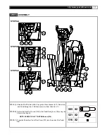
Page 14: ...ER STEP1 ASSEMBLY 408 342 341 109 408 342 341 STEP 1a Attach the Incline Frame Lower Cover 341 342 to the incline frame STEP 1b Carefully snap pieces together using plastic guides STEP 1c Secure using cone point screw 408 408 X4 ...

Page 15: ... Set to the Main Frame and hold the Incline Frame Holder Front 708 to the Incline Frame 109 secure using Allen head CAP Bolts 511 with Spring Washer 517 on the Incline Frame Holder Don t fully tighten Allen Head CAP Bolt 511 until STEP2 D STEP2 C Rotate the Incline Frame 109 to align the bolt holes with the mating bolt Holes in the Incline Transmission Tube Front 110 Assemble the Incline Transmiss...

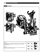
Page 16: ...ts 504 Connect the 8Pin Power Wire Upper 601 to 8Pin Power Wire Lower 602 by sliding plastic extrusion on connector under plastic clip on second connector STEP3 B Lift the Pedal Arm and attach the Undercarriage Cover 719 720 to the Main Frame and secure using Flat point screw 506 Screw 509 Screw 510 STEP3 C Attach the Incline Frame Front Cover 703 to the Incline Frame and secure Using two Screws 5...

Page 17: ...5 through the Wave Washer 521 Pedal Arm and Pedal Swing Arm 108 then secure by 8mm Allen Key C STEP4 B Secure the Back Out Screw 516 to the Pedal Swing Arm 108 using the 2 5mm Allen Key A NOTE PLEASE FULLY TIGHTEN Screw 516 STEP4 C Press the Pedal Arm Front Pivot Cover 702 into the ends of the Pedal Arm 505 X2 521 X2 516 X2 STEP4 A STEP4 B STEP4 C ...

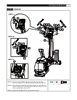
Page 18: ... Connect the Action Arm to the Moving Linkage and secure using the M6x10mm Bolt 502 and M8x15mm Bolt 503 by 6mm Allen Key D Do not over tighten or squeaking may occur SETP5 B Assemble the Action Handlebar Lower Cover 701 to the Action Handlebar and secure using the Cone Point Screw 501 502 X2 503 X2 501 X4 STEP5 A STEP5 B ...

Page 19: ...m Washers 513 M8x20mm Allen Head Bolts for STEP6 B STEP6 B Install the Moving Handlebar have Plastic Washer 519 first then the second is Washer 513 and finally tight the Allen Head Bolt 514 to lock the moving handlebar on the console STEP6 C Tight the Allen Head Bolts 514 by 5mm Allen Key B 514 X6 STEP6 B STEP6 C STEP6 A ...

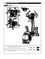
Page 20: ...efully sliding connector with plastic Extrusion under plastic clip on second connector STEP7 B Attach the Button Control Panel A1 and secure using Screw 510 STEP7 C Use Screw 512 to hold the Button Control Panel on left and right side to the corresponding hole in plastic 510 X2 512 X2 ...

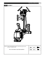
Page 21: ...www yowzafitness com 21 STEP8 ASSEMBLY 101 501 709 518 STEP8 A Attach the Water Bottle Holder 709 and secure using Cone point screw 501 with Washer 518 Your cross trainer is now fully assembled 501 X1 518 X1 ...

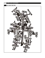
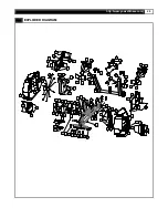
Page 22: ...01 241 211 412 211 412 413 413 241 706 701 101 118 434 405 434 401 415 405 401 415 104 105 402 102 514 214 313 514 345 345 514 519 513 214 313 103 519 514 302 301 515 214 513 303 303 312 312 462 521 462 521 348 348 706 463 463 709 518 501 486 486 461 464 464 490 486 486 461 464 490 464 515 214 ...

Page 23: ...http www yowzafitness com 23 EXPLODED DIAGRAM ...

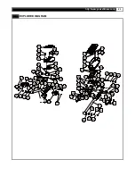
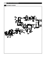
Page 24: ... 430 429 109 220 333 332 331 435 333 435 430 331 429 332 219 481 222 334 425 437 221 230 229 447 232 448 230 231 233 624 227 226 446 447 445 414 459 405 228 411 224 481 222 334 426 446 226 405 431 616 436 110 618 425 425 432 414 445 460 433 440 485 485 417 229 410 404 405 111 404 405 483 425 437 424 425 112 425 439 623 225 433 442 441 417 405 405 488 418 481 ...

Page 25: ...67 469 450 617 411 235 236 411 319 423 325 403 337 457 339 340 457 411 411 471 471 343 407 344 343 407 344 449 120 457 705 510 506 408 403 341 408 342 403 403 510 703 342 341 408 408 403 403 472 472 328 328 461 509 704 457 403 506 510 509 403 326 411 411 411 411 487 487 411 457 457 338 411 411 411 487 411 327 411 411 EXPLODED DIAGRAM ...

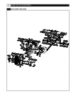
Page 26: ...APTIVA CROSSTRAINER EXPLODED DIAGRAM 314 350 476 411 310 512 351 457 403 466 457 306 475 477 323 322 468 403 308 614 474 635 475 457 411 474 305 476 309 633 304 510 470 346 347 632 473 470 465 457 411 635 457 457 ...

Page 27: ...http www yowzafitness com 27 WIRE DIAGRAM 606 603 617 616 618 616 604 619 629 630 601 607 614 610 615 612 613 633 633 634 632 616 605 622 620 606 602 601 609 607 601 631 602 640 641 631 ...

Page 28: ...IVA CROSSTRAINER STABILIZER ADJUSTMENT LEVEL ADJUSTMENT To adjust the level of the Captiva cross trainer simply rotate the Level Adjusters clockwise or counter clockwise Tilt the cross trainer to access stabilizers ...

Page 29: ... 29 TRANSPORT INSTRUCTIONS TRANSPORT INSTRUCTIONS The casters located on the rear of the unit allow for easy transport Simply lift the front of the unit until the wheels touch the floor Then roll the unit to a desired location ...

Page 30: ...e to exercise only for a few minutes in your target zone However your aerobic fitness will improve over the next six to eight weeks Don t be discouraged if it takes longer It s important to work at your own pace Ultimately you ll be able to exercise continuously for 30 minutes And the better your aerobic fitness the harder you will have to work to stay in your target zone But remember these essent...

Page 31: ...op primarily lower body muscle groups These muscle groups are shown in gray color on the chart below MUSCLE GROUPS A Shoulder muscles Calf muscles G B Pectoral muscles Trapezius muscles H C Bicep muscle Triceps muscles I D Abdominal muscles Back muscles J E Forearm muscles Gluteus muscles K F Quadriceps muscles Hamstring muscles L ...

Page 32: ...Inner Thigh Stretch Sit with the soles of your feet together with your knees pointing outward Pull your feet as close into your groin as possible Gently push your knees towards the floor Hold for 15 counts Hamstring Stretch Sit with your right leg extended Rest the sole of your left foot against your right inner thigh Stretch toward your toe as far as possible Hold for 15 counts Relax and then rep...

Page 33: ...ration caused by product location exposure or environment or conditions caused by unsuitable finishes cleaners or lubricants are not covered Loss from natural disasters such as hurricanes floods tornados etc are not covered Damage or breakage caused by unauthorized service installation alteration modification assembly or disassembly negligence or conditions of use which are unintended for the prod...

Page 34: ...SEQUENTIAL OR INCIDENTAL DAMAGES LOSSES OR EXPENSES INCLUDING BUT NOT LIMITED TO COMMERCIAL LOSSES BUSINESS INTERRUPTION OR DAMAGE TO PROPERTY OTHER THAN THE PRODUCT OR PRODUCTS TO WHICH THIS LIMITED WARRANTY APPLIES EFFECT OF STATE LAWS Some States do not allow limitations on how long an implied warranty lasts so the above limitation may not apply to you Some States do not allow the exclusion or ...

Page 35: ...HEIGHT B TIME C MOTION LEVEL D PULSE E DISTANCE PROGRAM F RESISTANCE UP DOWN BUTTON G iPod VOL CONTROLS H WEIGHT I AGE J GENDER K RPM L RESISTANCE LEVEL M RPM DIAGRAM N RESISTANCE PROFILE O SPEED P WATT Q CALORIES R MOTION UP DOWN BUTTON S STOP ENTER BUTTON T START BUTTON U FAN CONTROL BUTTON ...

Page 36: ...rn to the POWER ON status PAUSE STOP During the workout press STOP button or STOP pedaling for 30 seconds to enter PAUSE status The RESISTANCE LEVEL Dot Matrix display will show PAUSE All figures on the console will be frozen Press the START button or start pedaling to resume the program and all the display will continue the performance until the program finishes If you leave the pedal stopped for...

Page 37: ...STANCE UP DOWN button to adjust the user gender then press ENTER to confirm PROGRAM MODE After setting the user GENDER the computer will display a blinking P1 indicating that the user is now select from P1 10 Press the RESISTANCE UP DOWN buttons to select the programs and press the ENTER button to set up the program PROGRAM 1 TARGET TIME After enter this program the TIME display shows the factory ...

Page 38: ... target time and press STOP ENTER to confirm Press START button to start the INTERVAL RESISTANCE program Time counts down to 0 Distance and Calories count up Dot Matrix display shows the pre set and MOTION profile Press RESISTANCE UP DOWN to adjust the resistance and press MOTION UP DOWN to adjust the motion TIME zone INTENSITY level 1 st Segment 2 nd Segment 3 rd Segment 4 th Segment 5th Segment ...

Page 39: ... 5th Seg 6th Seg 7th Seg 8th Seg 9th Seg 10th Seg 11th Seg 12th Seg 13th Seg 14th Seg 15th Seg 16th Seg LEVEL L1 L1 L1 L3 L3 L4 L4 L5 L5 L6 L6 L7 L7 L9 L9 L1 L1 L2 L2 L2 L4 L4 L5 L5 L6 L6 L7 L7 L8 L8 L10 L10 L2 L2 L3 L3 L3 L5 L5 L6 L6 L7 L7 L8 L8 L9 L9 L11 L11 L3 L3 L4 L4 L4 L6 L6 L7 L7 L8 L8 L9 L9 L10 L10 L12 L12 L4 L4 L5 L5 L5 L7 L7 L8 L8 L9 L9 L10 L10 L11 L11 L13 L13 L5 L5 L6 L6 L6 L8 L8 L9 L9 ...

Page 40: ...ENTER to confirm PULSE display shows the calculated TARGET HEART RATE based on the user age setting from the above step The TARGET HEART RATE 85 MAXIMUM SAFE HEART RATE Press RESISTANCE UP DOWN button to adjust the target heart rate then press the STOP ENTER bottom to confirm Press the START button to start the 3 minute WARM UP The purpose of warm up program is to bring the user s heart rate to 65...

Page 41: ...use MOTION UP DOWN button to adjust MOTION LEVEL Then press the ENTER button to reserve the setting and continue to next minute setting of the program etc After setting up above item press the START button to activate status The maximum workout time of each user program is 60 minutes Main Individual custom program Press the START button again to begin the exercise program The LCD display will show...

Page 42: ...orn with the monitor strapped across the front of your body just above the chest line as shown in the drawing on the right The monitor needs a little body heat and moisture in order to work properly To ensure correct operation you may want to wet the two rubber pickups under the belt prior to exercising Chest belt is optional accessory ...

Page 43: ......

Reviews: