background image

NINGBO YOUWON TECHNOLOGY ELECTRONICS CO., LTD 

ADDRESS 

#928, XUEYUAN ROAD, LUGANG VILLAGE, GAOQIAO TOWN, NINGBO TELE 

PHONE

0574 88046201                                           FAX

0574-88046202 


z


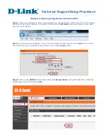
Interface Description: 

ZF01-C wireless module can be directly connected to RS-422 

equipment

 by RS-422 port,shown 

as Figure3.


A

B

PC

Wireless 

communication

 channel setting

RF

MCU

TTL

to

USB

Antenna

USB

USB

A

B

PC

RF

MCU

TTL

to

USB

Antenna

USB

USB

RS-422 

equipment

RS-422 

equipment

RS422

RS422

RS422

RS422

RS422

RS422


Figure3.  ZF01-C wireless communication application diagram 


z


Channel setting 

There is one group of 5-bit short-circuiter wire (JP2) as shown in Figure 2, defined as A

C

D

E respectively

A and B are used for setting channels

so there are 4 channels 

can be set .   
“0”= short , “1”= open 

A   

channel


frequency(MHz) 

433.050 


Summary of Contents for ZF01-C

Page 1: ...egrated can connect with transceiver equipment directly 2 Low power RF transmission Maximum transmit power 10mW 3 GFSK FSK modulation mode 4 Crystal frequency stabilization 5 High efficiency forward error correction channel encoding technology is used z Main Application Areas 1 AMR Automatic Meter Reading 2 Wireless alarm and security systems 3 Wireless POS PDA 4 Long distance non contact RF smart...

Page 2: ...N NINGBO TELE PHONE 0574 88046201 FAX 0574 88046202 z Main Technical Specifications RF channels 433 050MHz modulation mode GFSK baud rate 9600bps output power 10mW Interface data format UART 8E1 8N1 data format Power supply DC 3 6V 5V overall dimensions 70 X 45 X 17 mm Figure2 interface and sizes ...

Page 3: ...s communication channel setting RF MCU TTL to USB Antenna USB USB A B PC RF MCU TTL to USB Antenna USB USB RS 422 equipment RS 422 equipment RS422 RS422 RS422 RS422 RS422 RS422 Figure3 ZF01 C wireless communication application diagram z Channel setting There is one group of 5 bit short circuiter wire JP2 as shown in Figure 2 defined as A B C D E respectively A and B are used for setting channels s...

Page 4: ...ipment generates uses and can radiate radio frequency energy and if not installed and used in accordance with the instructions may cause harmful interference to radio communications However there is no guarantee that interference will not occur in a particular installation If this equipment does cause harmful interference to radio or television reception which can be determined by turning the equi...

Reviews: