JOHNSON CONTROLS
8
Form 160.78-O1
Issue date: 05/19/2021
Section 1 - System fundamentals
Heat exchangers
Evaporator and condenser shells are fabricated from
rolled carbon steel plates with fusion welded seams.
Heat exchanger tubes are internally enhanced type.
Evaporator
The evaporator is a shell and tube, hybrid falling film,
and flooded type heat exchanger. A distributor trough
provides uniform distribution of refrigerant over tubes
in the falling film section. Residual refrigerant floods
the tubes in the lower section. Suction baffles are locat-
ed above the tube bundle to prevent liquid refrigerant
carryover into the compressor. A 2 in. liquid level sight
glass is located on the side of the shell to aid in deter-
mining proper refrigerant charge. The evaporator shell
contains dual refrigerant relief valves unless condenser
isolation is installed.
Condenser
The condenser is a shell and tube type, with a discharge
gas baffle to prevent direct high velocity impingement
on the tubes. A separate subcooler is located in the con-
denser to enhance performance. Dual refrigerant relief
valves are located on condenser shells and optional re-
frigerant isolation valves are available.
Waterboxes
The removable compact waterboxes are fabricated
of steel. The design working pressure is 150 psig
(1034 kPa) and the boxes are tested at 225 psig
(1551 kPa). Integral steel water baffles provide the
required pass arrangements. Stub-out water nozzle
connections with Victaulic grooves are welded to the
waterboxes. These nozzle connections are suitable for
Victaulic couplings, welding or flanges, and are capped
for shipment. Plugged 3/4 in. drain and vent connec-
tions are provided in each waterbox. Optional marine
waterboxes are available.
Refrigerant flow control
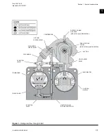
Refrigerant flow to the evaporator is controlled by a
variable orifice. See
.
A level sensor senses the refrigerant level in the con-
denser and outputs an analog voltage to the Microboard
that represents this level (0% = empty; 100% = full).
Under program control, the Microboard modulates a
variable orifice to control the condenser refrigerant
level to a programmed setpoint. Other setpoints affect
the control sensitivity and response. These setpoints
must be entered at chiller commissioning by a qualified
service technician. Only a qualified service technician
may modify these settings.
While the chiller is shut down, the orifice will be pre
positioned to anticipate run. When the chiller is started,
if actual level is less than the level setpoint, a linearly
increasing ramp is applied to the level setpoint. This
ramp causes the setpoint to go from the initial refriger-
ant level to the programmed setpoint over a program-
mable period of time. If the actual level is greater than
the setpoint upon run, there is no pulldown period,
it immediately begins to control to the programmed
setpoint.
While the chiller is running, the refrigerant level is nor-
mally controlled to the level setpoint.
Optional service isolation valves
If your chiller is equipped with optional service iso-
lation valves on the discharge and liquid line, these
valves must remain open during operation. These
valves are used for isolating the refrigerant charge in
either the evaporator or condenser to allow service ac-
cess to the system. A refrigerant pump-out unit will be
required to isolate the refrigerant.
Isolation of the refrigerant in this system
must be performed by a qualified service
technician.
Optional hot gas bypass
Hot gas bypass is optional and is used to provide great-
er turndown than otherwise available for load and head
conditions. The OptiView
TM
Control Center will auto-
matically modulate the hot gas valve open and closed
as required. Adjustment of the hot gas control valve
must only be performed by a qualified service techni-
cian.
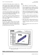
OptiView
TM
Control Center
The OptiView
TM
Control Center is factory-mounted,
wired and tested. The electronic panel automatically
controls the operation of the unit in meeting system
cooling requirements while minimizing energy usage.
For detailed information on the Control Center, refer
to the
YMC
2
OptiView
TM
Control Center Operations
Manual (Form 160.78-O2)
.
Summary of Contents for YMC2 A
Page 12: ...JOHNSON CONTROLS 12 Form 160 78 O1 Issue date 05 19 2021 THIS PAGE INTENTIONALLY LEFT BLANK ...
Page 16: ...JOHNSON CONTROLS 16 Form 160 78 O1 Issue date 05 19 2021 THIS PAGE INTENTIONALLY LEFT BLANK ...
Page 26: ...JOHNSON CONTROLS 26 Form 160 78 O1 Issue date 05 19 2021 THIS PAGE INTENTIONALLY LEFT BLANK ...


