


Johnson Controls
31
Section 1: General chiller information and safety
Form 150.72-ICOM6
Issue date: 12/19/2023
2
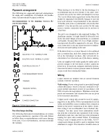
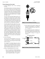
Figure 5:
Process and instrumentation diagram
PS
ZCPR-1
ZCPR-2
ZCPR-3
DV
HPL
HPC
P
DV
LPC
P
Condenser
Fans
Fans
-YLLSV
S
Chilled
Liquid
T
DV
CHT
LTC
Evaporator
Chilled
Liquid
See P.R.V.
Options
Compressors
Control Functions:
DV - Display Value
CHT - Chilled Liquid Temperature
HPC - High Pressure Cutout
LPC - Low Pressure Cutout
HPL - High Pressure Load Limiting
LTC - Low Temperature Cutout
Components:
Pressure Relief Valve
Service (Ball) Valve
Expansion Valve
Solenoid Valve
Sight Glass
Sensor Pressure
or Temperature
Service (Stop) Access Valve
Pressure Switch
Filter Drier
(Removable Core)
S
PS
T
Ambient Air Sensor
DV
HTC
LTC
585 PSIG
650 PSIG
450 PSIG
LD13139
Low pressure liquid refrigerant enters the cooler and
is evaporated and superheated by the heat energy ab-
sorbed from the chilled liquid passing through the
cooler shell. Low pressure vapor enters at the compres-
sor where pressure and superheat are increased. The
high pressure vapor is fed to the air cooled condenser
coil and fans where the heat is removed. The fully con-
densed and subcooled liquid passes through the expan-
sion valve where pressure is reduced and further cool-
ing takes place before entering to the cooler.


