406905-UIM-C-1009
14
Johnson Controls Unitary Products
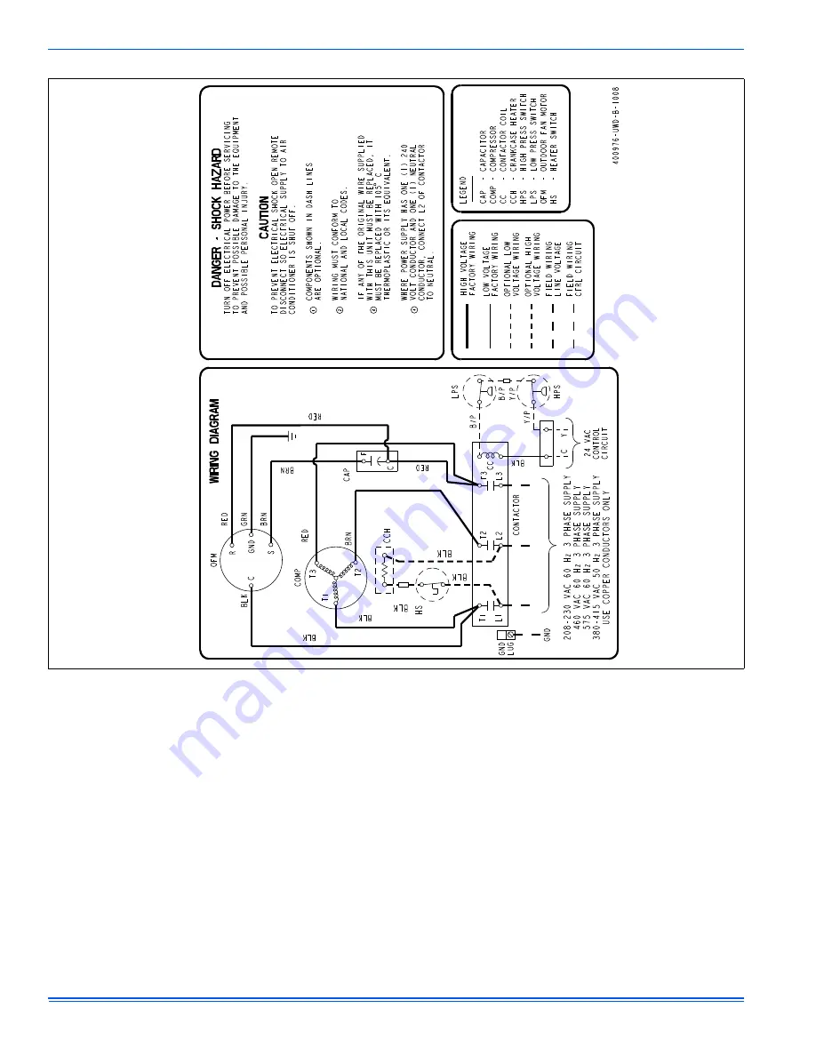
FIGURE 13:
Wiring Diagram (Three-Phase)
Page 1: ...dous situation which if not avoided could result in death or serious injury CAUTION indicates a potentially hazardous situation which if not avoided may result in minor or moderate injury It is also used to alert against unsafe practices and hazards involving only property dam age INSPECTION As soon as a unit is received it should be inspected for possible dam age during transit If damage is evide...
Page 2: ...approved R 410A coil con densing unit combination with the appropriate metering device 2 Change out of the line set when replacing an R 22 unit with an R410 A unit is highly recommended to reduce cross contamina tion of oils and refrigerants 3 If change out of the line set is not practical then the following pre cautions should be taken Inspect the line set for kinks sharp bends or other restricti...
Page 3: ...ubing Use clean hard drawn copper tubing where no appreciable amount of bending around obstruction is necessary If soft copper must be used care must be taken to avoid sharp bends which may cause a restriction 2 The lines should be installed so that they will not obstruct service access to the coil air handling system or filter 3 Care must also be taken to isolate the refrigerant lines to minimize...
Page 4: ...rom the vapor service port connection After this con nection has cooled remove the nitrogen source from the liquid fit ting service port 7 Replace the Schrader core in the liquid and vapor valves 8 Go to SECTION IV or SECTION V for orifice or TXV installation depending on application 9 Leak test all refrigerant piping connections including the service port flare caps to be sure they are leak tight...
Page 5: ...ture Cover completely to insulate from air stream SECTION V EVACUATION It will be necessary to evacuate the system to 500 microns or less If a leak is suspected leak test with dry nitrogen to locate the leak Repair the leak and test again To verify that the system has no leaks simply close the valve to the vac uum pump suction to isolate the pump and hold the system under vac uum Watch the micron ...
Page 6: ...unit service access panel FIELD CONNECTIONS POWER WIRING 1 Install the proper size weatherproof disconnect switch outdoors and within sight of the unit 2 Remove the screw from the field wiring access cover on the ser vice valve end of the unit Slide the cover down and remove from unit 3 Run power wiring from the disconnect switch to the unit 4 Route wires from disconnect through power wiring openi...
Page 7: ...ine set applications or in areas of known low voltage prob lems To eliminate erratic operation seal the hole in the wall at the ther mostat with permagum or equivalent to prevent air drafts affecting the operation of in the thermostat NOTICE NOTICE FIGURE 6 Typical Field Wiring Air Handler Electrical Heat Single Phase ALL FIELD WIRING TO BE IN ACCORDANCE WITH ELECTRIC CODE NEC AND OR LOCAL CODES P...
Page 8: ... electric heat on thermostat is not necessary MA SHP AHP ID MODELS Other Part Numbers SAP Legacy 265902 031 09167 2 Part Numbers SAP Legacy 159480 031 09156 1 COM 24 Volt Common R 24 Volt Hot W2 Second Stage Heat O Reversing Valve Energized in Cool X L Malfunction Light HUM Humidity Switch Open on Humidity Rise PSC AIR HANDLER CONTROL G Fan PSC AIR HANDLER 1 EAC 24 VAC out Electronic Air Cleaner H...
Page 9: ... Y1 Single Stage Compressor Y Y2 Second or Full Stage Compressor W1 First Stage Heat Y Full Stage Compressor G Fan BP11C50124 BN11C01124 DP11C40124 DN11C00124 THERMOSTAT RH 24 Volt Hot Heat XFMR RC 24 Volt Hot Cool XFMR W Full Stage Heat Selection of GAS ELEC switch on thermostat is not necessary C 24 Volt Common Y Full Stage Compressor G Fan BN11C00124 THERMOSTAT RH 24 Volt Hot Heat XFMR RC 24 Vo...
Page 10: ...ull Stage Heat Clipping Jumper W914 for electric heat on thermostat is not necessary 24VAC Humidifier Optional C 24 Volt Common Y Compressor SINGLE STAGE AIR CONDITIONER Y Compressor Contactor SINGLE STAGE AIR CONDITIONER SINGLE STAGE AIR CONDITIONER G8C L Y M 8S G 9F G 8 9 S ID MODELS G T GLS TG 8 9 S LF8 GF 8 9 C 24 Volt Common R 24 Volt Hot W Full Stage Heat SINGLE STAGE PSC FURNACE G Fan SINGL...
Page 11: ...ermostat is not necessary C 24 Volt Common Y Full Stage Compressor G Fan BN11C00124 THERMOSTAT RH 24 Volt Hot Heat XFMR RC 24 Volt Hot Cool XFMR W Full Stage Heat Thermostat Installer Setup 1 System Type must be set to 0 C 24 Volt Common Thermostat Installer Setup 15 Compressor Protection must be set to 5 External Humidistat Optional Open on Humidity Rise G8C L Y M 8S G 9F G 8 9 S ID MODELS G T GL...
Page 12: ...s MAINTENANCE 1 Dirt should not be allowed to accumulate on the outdoor coils or other parts in the air circuit Clean as often as necessary to keep the unit clean Use a brush vacuum cleaner attachment or other suitable means 2 The outdoor fan motor is permanently lubricated and does not require periodic oiling 3 If the coil needs to be cleaned use clean water to wash dust dirt and debris from outd...
Page 13: ...406905 UIM C 1009 Johnson Controls Unitary Products 13 SECTION IX WIRING DIAGRAM FIGURE 12 Wiring Diagram Single Phase 400975 ...
Page 14: ...406905 UIM C 1009 14 Johnson Controls Unitary Products FIGURE 13 Wiring Diagram Three Phase ...
Page 15: ...406905 UIM C 1009 Johnson Controls Unitary Products 15 NOTES ...
Page 16: ...nge without notice Published in U S A 406905 UIM C 1009 Copyright 2009 by Johnson Controls Inc All rights reserved Supersedes 406905 UIM B 1008 Johnson Controls Unitary Products 5005 York Drive Norman OK 73069 NOTES ...