background image

YORK INTERNATIONAL

89

FORM 150.62-NM1

Compressor Staging for Return Water Control –

6 Compressors

Cooling Setpoint = 45° F (7.2° C)  Range = 10° F (5.6° C)

Notes:

1. Step 1 is Hot Gas Bypass and is skipped when loading occurs. Hot Gas Bypass operation is inhibited during Pumpdown.

2. Step 3 is skipped when loading occurs.

3. Step 4 is skipped when unloading occurs.

TABLE 38 – RETURN CHILLED LIQUID CONTROL FOR 4 COMPRESSORS (6 STEPS)

*STEP

COMPRESSOR ON POINT

COMPRESSOR OFF POINT

0

1

SETPOINT

2

SP + CR/4

SP + CR/8

SEE NOTE 1

3

SP + 2*CR/4

SP + CR/4

SEE NOTE 2

4

SP + 2*CR/4

SP + CR/4

SEE NOTE 3

5

SP + 3*CR/4

SP + 2*CR/4

6

SP + CR

SP + 3*CR/4

TABLE 37 – RETURN CHILLED LIQUID CONTROL FOR 6 COMPRESSORS (8 STEPS)

*STEP

COMPRESSOR ON POINT

COMPRESSOR OFF POINT

0

1

SETPOINT

2

SP + CR/6

SP + CR/8

SEE NOTE 1

3

SP + 2*CR/6

SP + CR/6

SEE NOTE 2

4

SP + 2*CR/6

SP + CR/6

SEE NOTE 3

5

SP + 3*CR/6

SP + 2*CR/6

6

SP + 4*CR/6

SP + 3*CR/6

7

SP + 5*CR/6

SP + 4*CR/6

8

SP + CR

SP + 5*CR/6

TABLE 36 – COMPRESSOR STAGING FOR RETURN WATER CONTROL

*Unloading only

# OF COMP ON

0

*1+HG

1

2

3

4

5

6

RWT

45°F

46.25°F

46.7°F

48.3°F

50.0°F

51.7°F

53.4°F

55.0°F

(7.2°C)

(7.9°C)

(8.2°C)

(9.1°C)

(10.0°C)

(11.0°C)

(11.9°C)

(12.8°C)

* STEP can be viewed using the OPER DATA key and scrolling to COOLING DEMAND.

2

Summary of Contents for YCAL0080SC

Page 1: ...rd Glycol Metric Models Combined 200 3 60 230 3 60 380 3 60 460 3 60 575 3 60 MODELS ONLY 29224 R A INSTALLATION OPERATION MAINT MILLENNIUM AIR COOLED LIQUID CHILLERS HERMETIC SCROLL Supersedes 150 62...

Page 2: ...as severe personal injury or death to themselves and people at the site This document is intended for use by owner authorized operating service person nel It is expected that this individual possesses...

Page 3: ...t is subject to change without notice While YORK makes no commitment to update or provide current information automatically to the manual owner that information if applicable can be obtained by contac...

Page 4: ...ROUBLESHOOTING 95 OPTIONAL PRINTER INSTALLATION 104 TROUBLESHOOTING CHARTS 105 MAINTENANCE 108 ISN CONTROL 109 SECTION 4 WIRING DIAGRAMS 112 SECTION 5 APPENDIX 1 ISOLATORS 128 YORK APPLIED SYSTEMS FIE...

Page 5: ...OGRAMMABLE LIMITS DEFAULTS 76 29 PROGRAM KEY LIMITS DEFAULTS 79 30 SETPOINTS KEY QUICK REFERENCE 80 31 UNIT KEYS QUICK REFERENCE 84 32 LEAVING CHILLED LIQUID CONTROL 6 COMPRESSORS 86 33 LEAVING CHILLE...

Page 6: ...OR CIRC BKR 16 5 CONTROL WIRING 17 6 LEAVING WATER TEMPERATURE CONTROL COMPRESSOR STAGING 86 7 FIELD FACTORY ELECTRICAL CONNECTIONS REMOTE TEMPERATURE RESET BOARD 94 8 MICROBOARD LAYOUT 98 9 MICROBOAR...

Page 7: ...75 3 60 Across the Line 1 2 3 4 5 6 7 8 9 10 11 12 13 14 15 BASE PRODUCT TYPE NOMINAL CAPACITY UNIT DESIGNATOR REFRIGERANT VOLTAGE STARTER DESIGN DEVELOPMENT LEVEL Y 0 S C 1 7 A C 1 2 8 A A 4 0 U 4 6...

Page 8: ...Year Units Parts Only 5 Year Unit Parts Labor NOTES 1 Q DENOTES SPECIAL S Q 2 DENOTES STANDARD 3 X w in OPTIONS FIELD DENOTES NO OPTION SELECTED 4 Agency Files i e U L E T L C E ARI ETC will contain...

Page 9: ...OR RETURN WATER TEMP SENSOR DISCHARGE LINE BALL VALVE HOT DISCHARGE GAS LINE LIQUID LINE SERVICE VALVE LIQUID LINE FILTER DRIER LIQUID LINE SOLENOID VALVE SIGHT GLASS MOISTURE INDICATOR SOLENOID OPERA...

Page 10: ...followed to install and start up the chiller HANDLING These units are shipped as completely assembled units containing full operating charge and care should be taken to avoid damage due to rough handl...

Page 11: ...ller is not located next to occupied spaces or noise sensitive ar eas where chiller noise level would be a problem Chiller noise is a result of compressor and fan operation Con siderations should be m...

Page 12: ...ermometers and pressure gauges should be installed in the inlet and outlet wa ter lines 6 The chilled water lines that are exposed to outdoor ambients should be wrapped with supplemental heater cable...

Page 13: ...REMOTE START STOP CONTACTS To remotely start and stop the chiller dry contacts can be wired in series with the flow switch and CTB1 termi nals 13 to 14 Refer to Figure 5 and unit wiring diagram REMOTE...

Page 14: ...Electrical Notes and Legend located on Page 18 and 19 LD04483 IT IS POSSIBLE THAT MULTIPLE SOURCES OF POWER CAN BE SUPPLYING THE UNIT POWER PANEL TO PREVENT SERIOUS INJURY OR DEATH THE TECHNICIAN SHO...

Page 15: ...LY WIRING OPTIONAL SINGLE POINT POWER SUPPLY WIRING 0040 0080 LD04484 IT IS POSSIBLE THAT MULTIPLE SOURCES OF POWER CAN BE SUPPLYING THE UNIT POWER PANEL TO PREVENT SERIOUS INJURY OR DEATH THE TECHNIC...

Page 16: ...ING OPTIONAL SINGLE POINT POWER SUPPLY WIRING N F DISC SW OR CIRC BKR 0014 0080 LD04485 IT IS POSSIBLE THAT MULTIPLE SOURCES OF POWER CAN BE SUPPLYING THE UNIT POWER PANEL TO PREVENT SERIOUS INJURY OR...

Page 17: ...OURCES OF POWER CAN BE SUPPLYING THE UNIT POWER PANEL TO PREVENT SERIOUS INJURY OR DEATH THE TECHNICIAN SHOULD VERIFY THAT NO LETHAL VOLTAGES ARE PRESENT INSIDE THE PANEL AFTER DISCONNECTING POWER PRI...

Page 18: ...ed and maximum size is based on 225 of the rated load amps for the largest motor plus 100 of the rated load amps for all other loads included in the circuit Exception YCA0014 and YCAL0020 must have th...

Page 19: ...EAKER D E DUAL ELEMENT FUSE DISC SW DISCONNECT SWITCH FACT MOUNT CB FACTORY MOUNTED CIRCUIT BREAKER FLA FULL LOAD AMPS HZ HERTZ MAX MAXIMUM MCA MINIMUM CIRCUIT AMPACITY MIN MINIMUM MIN NF MINIMUM NON...

Page 20: ...inimum 14 AWG 75 C Copper Recommended B Minimum and Maximum Over Current Protection Dual Element Fuse or Circuit Breaker ELECTRICAL DATA IT IS POSSIBLE THAT MULTIPLE SOURCES OF POWER CAN BE SUPPLYING...

Page 21: ...3 130 16 3 130 2 3 8 575 60 36 60 40 45 40 45 8 4 13 1 85 13 1 85 2 3 1 0024SC 200 60 127 150 150 175 150 175 1 2 0 49 1 298 49 1 298 2 8 2 230 60 118 150 150 150 150 150 1 2 0 45 5 298 45 5 298 2 7...

Page 22: ...9 6 235 29 6 235 2 4 8 460 60 63 100 70 80 70 80 6 2 24 2 175 24 2 175 2 3 8 575 60 50 60 60 60 60 60 6 2 19 4 140 19 4 140 2 3 1 0064SC 200 60 187 200 200 225 200 225 3 0 250 52 4 298 52 4 298 52 4 2...

Page 23: ...6 2 24 2 175 24 2 175 2 3 8 50 60 60 60 60 60 6 2 19 4 140 19 4 140 2 3 1 128 150 150 150 150 150 1 2 0 34 2 265 34 2 265 34 2 265 2 8 2 119 150 150 150 150 150 1 2 0 31 6 265 31 6 265 31 6 265 2 7 8...

Page 24: ...1 0 380 60 52 60 60 60 60 60 6 2 6 2 460 60 45 60 50 60 50 60 8 4 8 4 575 60 36 60 40 45 40 45 8 4 8 4 0024SC 200 60 127 150 150 175 150 175 1 2 0 1 2 0 230 60 118 150 150 150 150 150 1 2 0 1 2 0 380...

Page 25: ...37 37 0 237 2 8 2 34 3 237 34 3 237 2 7 8 18 5 154 18 5 154 2 4 8 16 3 130 16 3 130 2 3 8 13 1 85 13 1 85 2 3 1 49 1 298 49 1 298 2 8 2 45 5 298 45 5 298 2 7 8 29 5 235 29 5 235 2 4 8 21 7 170 21 7 17...

Page 26: ...60 247 400 300 300 300 300 250 350 250 350 250 350 230 60 229 250 250 250 250 250 4 0 300 4 0 300 4 0 300 380 60 139 200 150 150 150 150 1 0 3 0 1 0 3 0 1 0 3 0 460 60 110 150 125 125 125 125 2 1 0 2...

Page 27: ...2 298 50 2 298 2 8 2 50 2 298 50 2 298 2 8 2 46 5 298 46 5 298 2 7 8 46 5 298 46 5 298 2 7 8 28 1 235 28 1 235 2 4 8 28 1 235 28 1 235 2 4 8 22 1 170 22 1 170 2 3 8 22 1 170 22 1 170 2 3 8 17 7 140 17...

Page 28: ...2 4 0 500 2 4 0 230 60 332 400 350 350 350 350 400 600 400 600 400 600 380 60 201 250 225 225 225 225 4 0 300 4 0 300 4 0 300 460 60 159 200 175 175 175 175 2 0 4 0 2 0 4 0 2 0 4 0 575 60 127 150 150...

Page 29: ...98 2 7 8 48 0 298 48 0 298 48 0 298 2 7 8 29 0 235 29 0 235 29 0 235 2 4 8 29 0 235 29 0 235 29 0 235 2 4 8 22 9 170 22 9 170 22 9 170 2 3 8 22 9 170 22 9 170 22 9 170 2 3 8 18 3 140 18 3 140 18 3 140...

Page 30: ...or leaving water temperature higher than 55 F contact the nearest YORK Office for application guidelines 3 The evaporator is protected against freeze up to 20 0 F with an electrical heater as standard...

Page 31: ...80 90 100 110 120 130 140 150 Press Drop Ft H 2 O Flow GPM Cooler Pressure Drop YCAL0034 LD04967 TABLE 9 COOLER PRESSURE DROP CURVES MODEL YCAL00 COOLER CURVE 14SC 20SC A 24SC B 30SC NEW 34SC NEW 40S...

Page 32: ...leaving chilled water temperature 2 For leaving water temperature higher than 12 8 C contact the nearest YORK Office for application guidelines 3 The evaporator is protected against freeze up to 28 9...

Page 33: ...HYLE POINT NE TONS COMPR DELTA GPM F C GLYCOL kW P TON 10 994 997 1 03 24 1 3 20 986 993 1 06 24 9 9 30 979 990 1 09 25 9 15 40 970 985 1 13 27 3 23 50 959 980 1 16 29 0 36 TABLE 14 ETHYLENE GLYCOL CO...

Page 34: ...3500 23500 23500 47360 47360 Evaporator Direct Expansion Diameter x Length 8 x6 8 x6 8 x6 5 8 x7 10 x7 11 x8 11 x8 Water Volume gallons 9 6 9 6 9 6 10 8 12 24 24 Maximum Water Side Pressure PSIG 150 1...

Page 35: ...1 7 2 1 7 2 1 7 2 1 7 1140 1140 1140 1140 1140 1140 3 3 3 3 3 3 47360 46080 55253 55253 54550 53760 11 x8 11 x8 14 x8 14 x8 14 x8 14 x8 24 24 41 41 41 38 150 150 150 150 150 150 300 300 300 300 300 3...

Page 36: ...7672 7672 11091 11091 11091 22351 22351 Evaporator Direct Expansion Diameter x Length 203x1829 203x1830 203x1981 203x2134 254x2134 279x2438 279x2438 Water Volume liters 36 36 36 41 45 91 91 Maximum W...

Page 37: ...4 2 1 7 2 1 7 2 1 7 2 1 7 1140 1140 1140 1140 1140 1140 3 3 3 3 3 3 22351 21747 26076 26076 25744 25371 279x2438 279x2438 356x2438 356x2438 356x2438 356x2438 91 91 155 155 155 144 10 10 10 10 10 10 2...

Page 38: ...terns and possible diminished performance YORK s unit controls will optimize operation without nuisance high pressure safety cutouts however the system designer must consider potential performance deg...

Page 39: ...ONS ENGLISH YCAL0014SC YCAL0020SC TABLE 17 WEIGHT DISTRIBUTION CENTER OF GRAVITY LD03847 MODEL WEIGHT DISTRIBUTION CENTER OF GRAVITY YCAL00 A B C D TOTAL X Y Z 14SC 587 525 587 525 2225 50 1 25 8 23 3...

Page 40: ...diminished performance YORK s unit controls will optimize operation without nuisance high pressure safety cutouts however the system designer must consider potential performance degradation Access to...

Page 41: ...SC YCAL0034SC TABLE 18 WEIGHT DISTRIBUTION CENTER OF GRAVITY LD03845 MODEL WEIGHT DISTRIBUTION CENTER OF GRAVITY YCAL00 A B C D TOTAL X Y Z 24SC 636 581 636 581 2435 50 6 25 9 28 5 30SC 692 632 692 63...

Page 42: ...flow patterns and possible diminished performance YORK s unit controls will optimize operation without nuisance high pressure safety cutouts however the system designer must consider potential perform...

Page 43: ...19 WEIGHT DISTRIBUTION CENTER OF GRAVITY MODEL WEIGHT DISTRIBUTION CENTER OF GRAVITY YCAL00 A B C D TOTAL X Y Z 40SC 1110 1071 1110 1071 4363 58 6 40 3 28 9 44SC 1133 1098 1133 1098 4462 58 7 40 3 28...

Page 44: ...flow patterns and possible diminished performance YORK s unit controls will optimize operation without nuisance high pressure safety cutouts however the system designer must consider potential perform...

Page 45: ...T DISTRIBUTION CENTER OF GRAVITY LD03851 MODEL WEIGHT DISTRIBUTION CENTER OF GRAVITY YCAL00 A B C D TOTAL X Y Z 64SC 1463 1288 1463 1288 5501 56 3 46 0 30 1 70SC 1492 1315 1492 1315 5616 56 3 45 6 30...

Page 46: ...inished performance YORK s unit controls will optimize operation without nuisance high pressure safety cutouts however the system designer must consider potential performance degradation Access to the...

Page 47: ...0020SC TABLE 21 WEIGHT DISTRIBUTION CENTER OF GRAVITY LD03853 All dimensions in millimeters unless otherwise noted MODEL WEIGHT DISTRIBUTION kg CENTER OF GRAVITY mm YCAL00 A B C D TOTAL X Y Z 14SC 266...

Page 48: ...inished performance YORK s unit controls will optimize operation without nuisance high pressure safety cutouts however the system designer must consider potential performance degradation Access to the...

Page 49: ...EIGHT DISTRIBUTION CENTER OF GRAVITY LD03855 All dimensions in millimeters unless otherwise noted MODEL WEIGHT DISTRIBUTION CENTER OF GRAVITY YCAL00 A B C D TOTAL X Y Z 24SC 288 264 288 264 1104 1285...

Page 50: ...inished performance YORK s unit controls will optimize operation without nuisance high pressure safety cutouts however the system designer must consider potential performance degradation Access to the...

Page 51: ...NTER OF GRAVITY LD03857 All dimensions in millimeters unless otherwise noted MODEL WEIGHT DISTRIBUTION CENTER OF GRAVITY YCAL00 A B C D TOTAL X Y Z 40SC 503 486 503 486 1979 1488 1024 734 44SC 514 498...

Page 52: ...inished performance YORK s unit controls will optimize operation without nuisance high pressure safety cutouts however the system designer must consider potential performance degradation Access to the...

Page 53: ...NTER OF GRAVITY LD03859 All dimensions in millimeters unless otherwise noted MODEL WEIGHT DISTRIBUTION CENTER OF GRAVITY YCAL00 A B C D TOTAL X Y Z 64SC 664 584 664 584 2495 1430 1168 765 70SC 677 596...

Page 54: ...MODEL _______________________ SERIAL ________________________________ CHECKING THE SYSTEM PRIOR TO INITIAL START NO POWER Unit Checks G 1 Inspect the unit for shipping or installation damage G 2 Assur...

Page 55: ...the Unit Switch to OFF The chilled liquid setpoint may need to be temporarily lowered to ensure all compressors cycle on G 7 After verifying compressor rotation return the Unit Switch to the off posit...

Page 56: ...rheat setting for a system is 10 F 5 56 C 18 46 cm from the cooler The superheat is calculated as the difference between the actual temperature of the returned refrigerant gas in the suction line ente...

Page 57: ...all sys tems shut down 4 Several seconds after the compressor starts that systems first condenser fan will be cycled on out door air temperature 25 F 4 C See the section on Operating Controls for deta...

Page 58: ...eac tivate the unit INTRODUCTION MICROPROCESSOR BOARD The Microprocessor Board is the controller and deci sion maker in the control panel System inputs such as pressure transducers and temperature sen...

Page 59: ...s are greater than or less than the limit values which are being displayed KEYPAD The 12 button non tactile keypad allows the user to re trieve vitals system parameters such as system pres sures tempe...

Page 60: ...he control panel is in the OFF position which will not allow the unit to run The REMOTE CONTROLLED SHUTDOWN message indicates that either an ISN or BAS system has turned the unit off not allowing it t...

Page 61: ...being timed out The anti coincident timer is only present on two system units When this message appears discharge pressure limit ing is in effect The Discharge Pressure Limiting fea ture is integral t...

Page 62: ...n the MANUAL OVERRIDE mode MANUAL OVERRIDE is to only be used in emergencies or for servicing Manual override mode automatically disables itself af ter 30 minutes The PUMPING DOWN message indicates th...

Page 63: ...programmed value and ramps up the cutout over the next 30 seconds If at any time during this 30 sec onds the suction pressure falls below the ramped cut out the system will stop This transient protec...

Page 64: ...the next power interruption The RTC battery is located at U17 on the microboard The Low Ambient Temp Cutout is a safety shutdown designed to protect the chiller from operating in a low ambient condit...

Page 65: ...X Switch Off System X Comps Run System X AR Timer System X AC Timer System X Disch Limiting System X Suction Limiting System X Percentage Load Limiting Manual Overide Status System X Pumping Down on...

Page 66: ...another key is pressed After pressing the OPER DATA key the various operat ing data screens can be scrolled through by using the UP and DOWN arrow keys located under the ENTRY section DISPLAY PRINT KE...

Page 67: ...s determined by how far the actual liquid temperature is from setpoint A detailed description of unit loading and unloading is covered under the topic of Capacity Control The display of COOLING DEMAND...

Page 68: ...sages indicate the type of remote control mode active NONE no remote control active Remote monitoring may be via ISN ISN YorkTalk via ISN Remote Mode LOAD LIM load limiting enabled Can be either stage...

Page 69: ...er Data Key Leaving Chilled Liquid Temps Ambient Air Temperature System 1 Discharge Suction Pressure System 2 Discharge Suction Pressure System X Accumulated Run Times System X Accumulated Starts Load...

Page 70: ...SIG SYS 2 SETPOINT 70 3 PSIG AMBIENT AIR TEMP 74 8 DEGF LEAD SYSTEM SYS 2 EVAPORATOR PUMP ON EVAPORATOR HEATER OFF ACTIVE REMOTE CONTROL NONE SOFTWARE VERSION C M02 01 00 SYSTEM 1 DATA COMPRESSORS STA...

Page 71: ...lly caused the safety threshold to be exceeded The history printout is similar to the operational data printout shown in the previous section The differences are in the header and the schedule informa...

Page 72: ...U L T L O W L I Q U I D T E M P L E A V I N G L I Q U I D T E M P C U T O U T X X X X F S Y S X F A N S T A G E X X X A C T I V E R E M O T E C T R L X X X X S Y S X S P X X X X P S I G D P X X X X P...

Page 73: ...arrow keys are also used for pro gramming the control panel such as changing cooling ENTRY KEYS setpoints setting the daily schedule changing safety setpoints chiller options and setting the clock ENT...

Page 74: ...n RETURN water temperature into the evaporator Unit must first be programmed for Unit Type Liquid Chiller under Op tion S key to allow programming of ap propriate setpoints Programming of the cooling...

Page 75: ...er the OPTIONS key the above programmed setpoints would have no effect Both LEAVING and RETURN control are described in detail under the section on Capacity Control This message indicates that the coo...

Page 76: ...SETPOINT KEY MODEL LOW LIMIT HIGH LIMIT DEFAULT LEAVING CHILLED LIQUID SETPOINT WATER COOLING 40 0 F 70 0 F 44 0 F 4 4 C 21 1 C 6 7 C GLYCOL COOLING 10 0 F 70 0 F 44 0 F 12 2 C 21 1 C 6 7 C LEAVING C...

Page 77: ...ew Monday sched ule This means if the Monday times are not applicable for the whole week then the exceptional days would need to be reprogrammed to the desired schedule To page to a specific day press...

Page 78: ...iller from an evaporator freeze up If the suction pres sure drops below the cutout point the system will shut down There are some exceptions when the suction pressure is permitted to tem porarily drop...

Page 79: ...he chiller and determines the stages of cooling available Notice in Table 29 the chiller is a single or dual refrigerant circuit This must be programmed correctly to assure proper chiller operation T...

Page 80: ...aving Mon Sun Discharge Water Temp Control Pressure Display Only Holiday Cutout Schedule Chilled Liquid Suction Setpoint Pressure Cutout Range Remote Setpoint Low Ambient Temp Cutout Range Display Onl...

Page 81: ...the displays in the order they appear Option 1 Language Option 2 System Switches two system units only This allows both systems to run or S Y S 1 S W I T C H O N S Y S 2 S W I T C H O N D I S P L A Y...

Page 82: ...ices or This mode should be selected when an ISN or RCC control is to be used to control the chiller This mode will allow the ISN to control the following items Remote Start Stop Cooling Setpoint Load...

Page 83: ...ill be accepted and the cursor will move under the 0 In a similar manner the hour minute meridian month day and year may be programmed whenever the cur sor is under the first letter numeral of the ite...

Page 84: ...adv Display Language Day Time Date System Switches on off Unit Type Chiller or Condensing Unit Chilled Liquid Type water or glycol Ambient Control standard or low Local Remote Mode Unit Control Mode...

Page 85: ...The Setpoint Low Limit is the Setpoint minus the Cooling Range See Fig ure 6 If the leaving chilled liquid temperature is above the Setpoint High Limit the lead compressor on the lead system will be...

Page 86: ...46 0 F 7 8 C Range 2 F 1 1 C LWT LEAD SYSTEM LAG SYSTEM STEP COMP 1 COMP 2 COMP 3 COMP 1 COMP 2 COMP 3 0 OFF OFF OFF OFF OFF OFF 1 ON HG OFF OFF SEE NOTE 1 OFF OFF OFF 2 ON OFF OFF OFF OFF OFF 3 ON O...

Page 87: ...noid is turned off when the LWT SP CR 2 2 Step 3 is skipped when loading occurs 3 Step 4 is skipped when unloading occurs STEP can be viewed using the OPER DATA key and scrolling to COOLING DEMAND TAB...

Page 88: ...l range will be split up into six seven including hot gas segments with the Control Range determining the separation between segments Note also that the Cooling Setpoint is the point at which all comp...

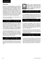
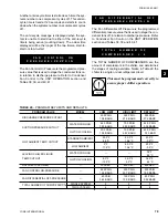
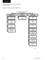
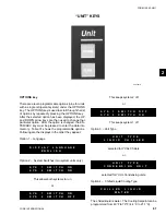
Page 89: ...OTE 1 3 SP 2 CR 4 SP CR 4 SEE NOTE 2 4 SP 2 CR 4 SP CR 4 SEE NOTE 3 5 SP 3 CR 4 SP 2 CR 4 6 SP CR SP 3 CR 4 TABLE 37 RETURN CHILLED LIQUID CONTROL FOR 6 COMPRESSORS 8 STEPS STEP COMPRESSOR ON POINT CO...

Page 90: ...Only The condenser fan control by Ambient Temperature and Discharge Pressure is a feature that is integral to the standard software control If the optional discharge transducer is not installed the co...

Page 91: ...er Condenser Fan Control The fan control on pressure ctrl_press and the fan def erential off pressure diff_press are programmable un der the PROGRAM key TABLE 42 LOW AMBIENT CONDENSER FAN CONTROL DISC...

Page 92: ...inputs The first stage of limiting is ei ther 66 or 50 depending on the number of com pressors on the unit The second stage of limiting is 33 and is only available on 3 and 6 compressor units Table 43...

Page 93: ...oint 7 22 C 2 78 C 10 C ThiscanbeviewedbypressingtheCoolingSetpoints keytwice Thenewvaluewillbedisplayedas REMSETP 10 0 C BAS EMS TEMPERATURE RESET OPTION The Remote Reset Option allows the Control Ce...

Page 94: ...y jumper JUI must be in place on the reset board This input is used when a single reset value is needed When the contacts are closed the remote temperature reset board will con vert this contact closu...

Page 95: ...counters to be viewed modified The ENTER ADV key is used to advance through the digital outputs Using the UP DOWN ARROW keys will turn the respective digital output on off Following is the order of di...

Page 96: ...tes that the system 1 suction pres sure input is connected to plug 4 pin 10 J4 10 on the microboard It indicates that the voltage is 2 1 volts dc which corresponds to 81 PSIG 5 6 bars suction pres sur...

Page 97: ...30VDC UNREGULATED SUPPLY J9 2 UNIT ON OFF SWITCH J9 3 PWM TEMP RESET OR LOAD LIMIT STAGE 2 ON 3 6 COMP UNITS J9 4 LOAD LIMIT STAGE 1 J9 5 FLOW SWITCH AND REMOTE START STOP SYS 1 ZONE THERMOSTAT YCUL O...

Page 98: ...YORK INTERNATIONAL 98 FIG 8 MICROBOARD LAYOUT J4 J8 J6 J5 J7 J9 TB3 TB4 TB5 00071VIP TB1 TB2 Service and Troubleshooting CLOCK ON OFF JUMPER...

Page 99: ...he binary inputs This voltage is in refer ence to ground The unit case should be sufficient as a reference point when measuring binary input voltages ANALOG INPUTS Temperature Refer to the unit wiring...

Page 100: ...VOLTAGE RESISTANCE CORRELATION TEMP F VOLTAGE RESISTANCE TEMP C 0 1 71 25619 18 2 1 78 24046 17 4 1 85 22580 16 6 1 93 21214 14 8 2 00 19939 13 10 2 07 18749 12 12 2 15 17637 11 14 2 22 16599 10 16 2...

Page 101: ...adout on the display will be 0 PSIG when the LP switch is open and 200 PSIG 13 79 BARG when the LP switch is closed The discharge transducers have a range from 0 to 400 PSIG The output will be linear...

Page 102: ...ansducer is not used on the YCAL0014 YCAL0060 a Low Pressure switch will be used Following are the microboard connections for the Low Pressure switch System 1 Low Pressure Switch J4 5 5VDC regulated s...

Page 103: ...E DAY 3 TO 5 PROGRAM 3 TO 7 OPTIONS 3 TO 6 CLOCK 3 TO 8 3 points or pins that represent one of twelve buttons on the keypad Table 49 lists the key pin assignments for the keypad Power to the microboar...

Page 104: ...hat is packaged specifi cally for YORK is P N 950915576 The cable to connect the printer can either be locally assembled from the parts listed or ordered directly from WEIGH TRONIX under part number 2...

Page 105: ...r Display board NOTE Contact YORK Service before Replacing circuit Boards FLOW SWITCH REM 1 No chilled liquid flow 1 Check chilled liquid flow STOP NO RUN PERMISSIVE 2 Flow switch improperly 2 Check t...

Page 106: ...ch refrigerant 2 Remove refrigerant 3 Air in refrigerant system 3 Evacuate and recharge system 4 Defective discharge 4 Replace discharge pressure pressure transducer transducer Refer to Service sectio...

Page 107: ...RT Installation Manual to aid in understanding compres sor operation and capacity control 2 Defective water temperature 2 Compare the display with a sensor thermometer Should be within 2 degrees Refer...

Page 108: ...into a vacuum Doing so will cause inter nal arcing of the compressor motor which will result in failure of compres sor CONDENSER FAN MOTORS Condenser fan motors are permanently lubricated and require...

Page 109: ...a zero will be sent Tables 52 53 show the data values and page listings for this unit ISN CONTROL TABLE 51 ISN RECEIVED DATA TABLE 52 ISN TRANSMITTED DATA ISN PAGE CONTROL DATA P03 SETPOINT P04 LOAD...

Page 110: ...TAL LOCAL REMOTE CONTROL MODE 0 LOCAL 1 REMOTE P53 DIGITAL UNITS 0 IMPERIAL 1 SI P54 DIGITAL LEAD LAG CONTROL MODE 0 MANUAL 1 AUTO P55 DIGITAL P56 CODED SYS 1 OPERATIONAL CODE P57 CODED SYS 1 FAULT CO...

Page 111: ...ESSURE 8 NO RUN PERMISSIVE 8 HIGH MOTOR CURRENT 9 NO COOL LOAD 9 LLSV NOT ON 10 ANTI COINCIDENCE TIMER ACTIVE 10 LOW BATTERY WARNING 11 ANTI RECYCLE TIMER ACTIVE 11 HIGH OIL TEMPERATURE 12 MANUAL OVER...

Page 112: ...YORK INTERNATIONAL 112 ELEMENTARY DIAGRAM YCAL0014SC YCAL0030SC FIG 11 ELEMENTARY DIAGRAM Wiring Diagrams...

Page 113: ...YORK INTERNATIONAL 113 FORM 150 62 NM1 20 LD03531 ELEMENTARY DIAGRAM YCAL0014SC YCAL0030SC FIG 11 ELEMENTARY DIAGRAM Cont d 4...

Page 114: ...YORK INTERNATIONAL 114 ELEMENTARY DIAGRAM YCAL0014SC YCAL0030SC LD03532 FIG 12 ELEMENTARY DIAGRAM Wiring Diagrams...

Page 115: ...YORK INTERNATIONAL 115 FORM 150 62 NM1 This page intentionally left blank 4...

Page 116: ...YORK INTERNATIONAL 116 ELEMENTARY DIAGRAM YCAL0034SC FIG 13 ELEMENTARY DIAGRAM Wiring Diagrams...

Page 117: ...YORK INTERNATIONAL 117 FORM 150 62 NM1 FIG 13 ELEMENTARY DIAGRAM Cont d LD03533 ELEMENTARY DIAGRAM YCAL0034SC 4...

Page 118: ...YORK INTERNATIONAL 118 FIG 14 ELEMENTARY DIAGRAM ELEMENTARY DIAGRAM YCAL0034SC LD03534 Wiring Diagrams...

Page 119: ...YORK INTERNATIONAL 119 FORM 150 62 NM1 This page intentionally left blank 4...

Page 120: ...YORK INTERNATIONAL 120 ELEMENTARY DIAGRAM YCAL0040SC YCAL0060SC FIG 15 ELEMENTARY DIAGRAM Wiring Diagrams...

Page 121: ...YORK INTERNATIONAL 121 FORM 150 62 NM1 ELEMENTARY DIAGRAM YCAL0040SC YCAL0060SC LD03535 FIG 15 ELEMENTARY DIAGRAM Cont d 4...

Page 122: ...YORK INTERNATIONAL 122 ELEMENTARY DIAGRAM YCAL0040SC YCAL0060SC FIG 16 ELEMENTARY DIAGRAM Wiring Diagrams...

Page 123: ...YORK INTERNATIONAL 123 FORM 150 62 NM1 ELEMENTARY DIAGRAM YCAL0040SC YCAL0060SC LD03536 FIG 16 ELEMENTARY DIAGRAM Cont d 4...

Page 124: ...YORK INTERNATIONAL 124 ELEMENTARY DIAGRAM YCAL0064SC YCAL0080SC FIG 17 ELEMENTARY DIAGRAM Wiring Diagrams...

Page 125: ...YORK INTERNATIONAL 125 FORM 150 62 NM1 ELEMENTARY DIAGRAM YCAL0064SC YCAL0080SC LD03537 FIG 17 ELEMENTARY DIAGRAM Cont d 4...

Page 126: ...YORK INTERNATIONAL 126 ELEMENTARY DIAGRAM YCAL0064SC YCAL0080SC FIG 18 ELEMENTARY DIAGRAM Wiring Diagrams...

Page 127: ...YORK INTERNATIONAL 127 FORM 150 62 NM1 LD03538 ELEMENTARY DIAGRAM YCAL0064SC YCAL0080SC FIG 18 ELEMENTARY DIAGRAM Cont d 4...

Page 128: ...M 1300 YCAL0050 AEQM 1600 AEQM 1600 AEQM 1600 AEQM 1600 YCAL0060 AEQM 1600 AEQM 1600 AEQM 1600 AEQM 1600 YCAL0064 AEQM 1625 AEQM 1600 AEQM 1625 AEQM 1600 YCAL0070 AEQM 1625 AEQM 1600 AEQM 1625 AEQM 16...

Page 129: ...WEIGHT DISTRIBUTION POINT SPRING LOCATION Refer to Dimensions for Weight Distribution Point Location A D MODEL A B C D YCAL0014 CP 1 27 CP 1 27 CP 1 27 CP 1 27 YCAL0020 CP 1 27 CP 1 27 CP 1 27 CP 1 27...

Page 130: ...APPENDIX 1 DIMENSIONS FIG 19 TYPE CP 1 FIG 20 TYPE CP 2 LD03839 LD03840 Appendix 1 Isolators...

Page 131: ...D E F G H J AEQM 97 7 5 4 2 A 7 A AEQM 98 7 5 4 2 A 7 A AEQM 99 7 5 4 2 A 7 A AEQM 1000 8 6 6 4 8 B AEQM 1300 8 6 6 4 8 B AEQM 1600 8 6 6 4 8 B AEQM 1625 8 6 6 4 8 B AEQM 1628 8 6 6 4 8 B LD04045 FIG...

Page 132: ...uired bolt mountings to floor through slots 4 Set the machine or base on the mountings The weight of the machine will cause the upper housing of the mount to go down possibly resting on the lower hous...

Page 133: ...e equip ment or equipment base mounting holes Shim and or grout as required to level all isolator base plates A A 1 4 maximum difference in elevation can be tolerated 4 Anchor all isolators to floor o...

Page 134: ...08 225 0606 NEVADA Las Vegas YORK International Corp 702 873 2200 NEW YORK Buffalo YORK International Corp 716 633 2172 New York YORK International Corp 212 843 1602 NORTH CAROLINA Charlotte YORK Inte...

Page 135: ...YORK INTERNATIONAL 135 FORM 150 62 NM1 This page intentionally left blank...

Page 136: ...nia USA 17405 1592 Subject to change without notice Printed in USA Copyright by York International Corporation 2000 ALL RIGHTS RESERVED Form 150 62 NM1 700 Supersedes 150 62 NM1 899 150 62 NM1 399 Tel...

Reviews: