JOHNSON CONTROLS
140
FORM 150.66-NM3
ISSUE DATE: 09/25/2020
SECTION 8 - UNIT OPERATION
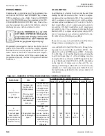
PROGRAMMING
Condenser fan control type must be programmed un-
der both the OPTIONS and PROGRAM keys when a
VFD is installed on the chiller. Under the OPTIONS
key, FAN CONTROL must be programmed for DIS-
CHARGE PRESSURE CONTROL only. This will en-
sure the condenser fan control of the chiller is solely by
discharge pressure, with no ambient control..
Under the PROGRAM key, the FAN
CONTROL ON PRESSURE should be
programmed for 240 psig and the FAN
DIFFERENTIAL OFF PRESSURE
must be programmed for 80 psig.
Programming as suggested ensures the chiller control
points for the second fan in the fan staging sequence
and the inverter control points are matched for opti-
mum control of the fans at reduced ambient tempera-
tures. When the chiller and VFD fan control points are
programmed properly, the fans will operate as outlined
in Table 24.
TABLE 24 – INVERTER OPTION CONDENSER FAN CONTROL OPERATION
FAN STAGE
ON
OFF
CONTACTOR
MICROBOARD
FAN #
SYS 1
SYS 2
SYS 1
SYS 2
SYS 1
SYS 2
1:
Inverter Control
(1 Fan
Variable Speed)
Fan speed is a
function of dis-
charge pressure.
When the liquid
line solenoid is
energized, speed
increases with
pressure.
Fan will turn very
slowly or display
only slight move-
ment when pres-
sure drops below
160 psig. Fan will
turn completely off
when liquid line
solenoid deener-
gizes.
7M
10M
TB7-9
TB10-9
1
2
2:
Inverter control
(1 fan full speed
under inverter
control and 2nd fan
full speed under
contactor control)
280 psig, both fans
will be running full
speed
Discharge pres-
sure
< 200 psig (pres-
sure is < fan Con-
trol on pressure of
280 psig minus fan
Differential Pres
-
sure of 80 psig
=180 psig)
7M
&
8M
10M
&
11M
TB7-9
&
TB7-10
TB10-9
&
TB10-10
1
&
3
2
&
4
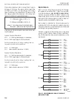
LOAD LIMITING
Load Limiting is a feature that prevents the unit from
loading beyond the desired value. 2 and 4 compres-
sor units can be load limited to 50%. This would allow
only 1 compressor per system to run. 3 and 6 compres-
sor units can be load limited to 33% or 66%. The 66%
limit would allow up to 2 compressors per system to
run, and the 33% limit would allow only 1 compressor
per system to run. Five-compressor units may be load
limited to 40% (1 compressor per system runs) or 80%
(up to 2 compressors per system) are permitted to run.
No other values of limiting are available.
There are two ways to load limit the unit. The first is
through remote communication via an ISN.
A second method to load limit the unit is through clos-
ing contacts connected to the Load Limit (CTB1 – Ter-
minals 13 to 21) and PWM inputs (CTB1 – Terminals
13 to 20). Stage 1 of load limiting involves closing the
Load Limit input. Stage 2 of load limiting involves
closing both the Load Limit and PWM inputs. The first
stage of limiting is either 80%, 66% or 50%, depending
on the number of compressors on the unit. The sec-
ond stage of limiting is either 40% or 33% and is only
available on 3, 5 & 6 compressor units. Table 25 shows
the load limiting permitted for the various number of
compressors.
Summary of Contents for YCAL Series
Page 4: ...JOHNSON CONTROLS 4 FORM 150 66 NM3 ISSUE DATE 09 25 2020 THIS PAGE INTENTIONALLY LEFT BLANK...
Page 16: ...JOHNSON CONTROLS 16 FORM 150 66 NM3 ISSUE DATE 09 25 2020 THIS PAGE INTENTIONALLY LEFT BLANK...
Page 130: ...JOHNSON CONTROLS 130 FORM 150 66 NM3 ISSUE DATE 09 25 2020 THIS PAGE INTENTIONALLY LEFT BLANK...
Page 144: ...JOHNSON CONTROLS 144 FORM 150 66 NM3 ISSUE DATE 09 25 2020 THIS PAGE INTENTIONALLY LEFT BLANK...
Page 173: ...FORM 150 66 NM3 ISSUE DATE 09 25 2020 173 JOHNSON CONTROLS 10 NOTES...

