5168273-YIM-A-1115
16
Johnson Controls Unitary Products
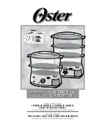
Figure 15: Typical Field Wiring 24 Volt Thermostat
OCC
C
RC
G
Y2
Y1
W2
W1
X
R
THERMOSTAT
TERMINALS
CONTROL
TERMINAL
BLOCK
TERMINALS ON A
LIMITED NUMBER
OF THERMOSTATS
1
4
3
1
2
4
Second stage
ŚĞĂƟŶŐŶ
ot required on single stage he
ĂƟŶ
g units.
Jumper is required if there is no Smoke Detector circuit.
Jumper is required for any co
ŵďŝŶĂƟŽŶ
of R, RC, or RH.
5
5
OCC is an output from the thermostat to indicate the Occupied
ĐŽŶĚŝƟ
on.
X is an input to the thermostat to display Error Status condi
Ɵ
ons.
3
W2
Y1
G
OCC
Y2
X
R
SD-24
C
W1
2
24V
C
24 VAC
Class 2
SD-24
Jumper Located on Harness
Smoke
Detector
SD-R
24V Output
R
(If No Smoke Detector)
(If Smoke Detector Is Used)
208/230-3-60 unit control transformers are factory wired
for 230v power supply. Change tap on transformer for
208-3-60 operation. See unit wiring diagram.