


Additionally, the slab should NOT be tied to the main building
foundations as noise due to vibration may be transmitted.
For ground level installations, precautions should be taken to
protect the unit from tampering and unauthorized persons from
injury. Screws on access panels will prevent casual tampering.
Further safety precautions such as a fenced enclosure or
locking devices on the panels may be advisable. Check local
authorities for safety regulations.
ROOFTOP LOCATIONS
Choose a spot with adequate structural strength to safely
support the entire weight of the unit and service personnel.
Care must be taken so as not to damage the roof. Consult the
building contractor or architect if the roof is bonded. The unit
must be mounted level on a minimum of two beams. The
beams should (1) be positioned perpendicular to the roof joists,
(2) extend beyond the dimensions of the section to distribute
the load on the roof, (3) be capable of supporting the weight of
the unit and (4) be positioned parallel to the longer base rails
of the unit OR parallel to the shorter base rails of the unit as
shown in Figure 2.
CLEARANCES
The units must be installed with sufficient clearance for air to
enter the condenser coil and not be recirculated after dis-
charge. Sufficient clearance must also be provided for service
access. Refer to the unit illustration in Figure 5 for minimum
clearances.
The area within the clearances and the area under the unit must
be kept clear of all obstructions that would impede free air flow
to the unit. In installations where low ambient operation is
intended and snow accumulation is expected, additional unit
height must be provided to insure full air flow.
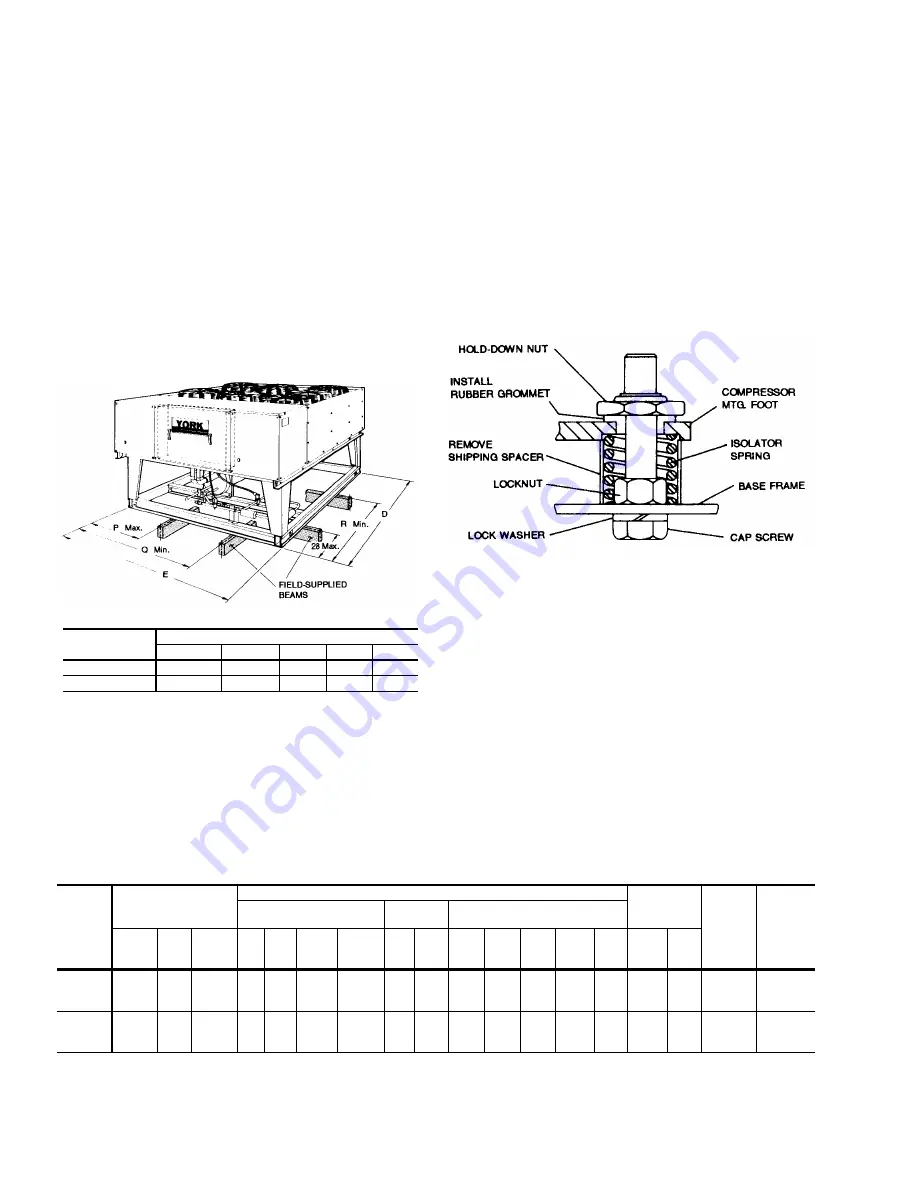
COMPRESSOR HOLD-DOWN NUTS
For shipping, the compressor hold-down nuts are tightened,
drawing the compressor mounting feet down to the shipping
stops.
CAUTION: After the unit is in its final position, remove the
compressor hold-down nuts and shipping spac-
ers. Install rubber grommets (shipped in bag tied
to compressor). Replace the hold-down nuts and
tighten until they start to bind the rubber grom-
mets. Continue to tightened additional half turn.
See Figure 3.
DISCHARGE LINE HOLD-DOWN BRACKET
CAUTION: Do NOT remove the discharge line support brack-
ets located within the compressor compartment. It
reduces vibration during unit operation.
CHILLED LIQUID PIPING
The cooler inlet and outlet liquid connections are 3 inch nominal
pipe size. The connections are made with grooved ends de-
signed to accept Victaulic
grooved pipe couplings only. Re-
move the shipping caps and discard.
CAUTION: The liquid piping RETURNING to the chiller MUST
be attached to the cooler connection CLOSEST to
the compressor end of the unit. The liquid piping
LEAVING the cooler MUST be attached to the
cooler connection FURTHEST from the compres-
sor end of the unit. See Figure 5 for liquid inlet and
outlet connections.
FIG. 2 - SUPPORT BEAM LOCATIONS
Model
Dimensions (Inches)
D
E
P
Q
R
W1LC420
118-5/8
86-3/4
30
70
76
W1LC530
118-5/8
86-3/4
30
70
76
Model
Compressor
1
Condenser
Unit Weight
(Lbs.)
Oper.
Charge,
(R-22)
(Lbs.)
Cap.
Reduction
(%)
Fan (Propeller)
Fan
Motors
3
Coil
(Copper Tube - Aluminum Fin)
Nom.
Cap.
(Tons)
No.
of
Cyl.
Stages
of
Cap.
Qty.
2
Dia.
(In.)
Pitch
(Deg.)
Nom.
CFM
HP RPM
Face
Area
(Ft.
2
)
Rows
Deep
Rows
Wide
Tube
OD
(in.)
Fins
per
inch
Ship. Oper.
W1LC420
System 1
System 2
20
20
4
4
2
2
3
3
24
30
16,050
16,050
3/4 1075 30.0
30.0
3
3
36
36
3/8
12
3,380 3,480
26.0
26.0
25,50
75,100
W1LC530
System 1
System 2
20
30
4
6
2
2
3
4
24
30
14,400
19,400
3/4 1075 35.0
35.0
4
4
30
42
3/8
12
3,720 3,820
26.0
35.0
20,40
60,100
1
All compressors are semi-hermetic.
2
During low ambient conditions, the motor for one of these fans will operate at 450 RPM.
3
These PSC motors are directly connected to the condenser fans and have inherent protection, ball bearings and a 48 frame. Their rotation is clockwise when viewing the shaft end of
the motor.
TABLE 2 - PHYSICAL DATA
FIG. 3 - COMPRESSOR HOLD-DOWN NUTS
570.05-N4Y
4
Unitary Products Group