background image

1083293-UIM-D-1116

Johnson Controls Unitary Products

35

ADJUSTMENT OF MANIFOLD GAS PRESSURE

Inlet and manifold gas pressure may be measured by connecting the
“U” tube manometer to the gas valve with a piece of tubing. Follow the
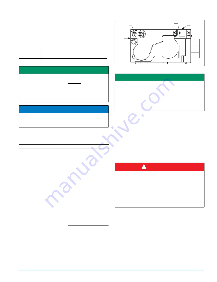
appropriate section in the instructions below. Refer to Figure 40 for the
locations of the pressure ports on the gas valve.

Turn gas off at the ball valve or gas cock on gas supply line 
before the gas valve. Find the pressure ports on the gas 
valve marked Out P and In P.

1.

The manifold pressure must be taken at the port marked OUT P. 

2.

The inlet gas line pressure must be taken at the port marked IN P.

3.

Using a 3/16” allen wrench, remove the plugs from the inlet and
outlet pressure ports. Connect a 1/8” UPT barbed hose fitting to
each pressure port.

4.

Refer to Figure 40 for location of pressure regulator adjustment
screw on main gas valve.

5.

Turn gas and electrical supplies on and follow the operating
instructions to place the unit back in operation.

6.

Use a small slotted screwdriver to turn the regulator adjustment
screw. Adjust the pressure by turning the screw one click at a time
until desired pressure is reached. Wait a few seconds after each
adjustment to allow the pressure to stabilize before making addi-
tional adjustments. This is an electronic adjustment screw that
does not require very much force. Application of excessive force to
the adjustment screw will damage the gas valve.

7.

After the manifold pressure has been adjusted, re-calculate the

furnace input to make sure you have not exceeded the specified
input on the rating plate. Refer to "CALCULATING THE FURNACE
INPUT (NAT. GAS)".

8.

Once the correct BTU (kW) input has been established, turn the
gas valve to OFF and turn the electrical supply switch to OFF; then
remove the flexible tubing and fittings from the gas valve pressure
tap replace the pressure tap plugs.

9.

Turn the electrical and gas supplies back on, and with the burners
in operation, check for gas leakage around the gas valve pressure
port for leakage using an approved gas detector, a non-corrosive
leak detection fluid, or other leak detection methods.

ADJUSTMENT OF TEMPERATURE RISE

After about 5 minutes of operation, determine the furnace temperature

rise. Take temperature readings of both the return air and the heated air
in the ducts about six feet away from the furnace, where they will not be
affected by radiant heat. Increase or decrease the temperature rise by
changing the ATR jumper on the furnace control board. The jumper is
factory-set to deliver an air temperature rise near the midpoint of the
nameplate temperature rise range. If more air is desired (lower tem-
perature rise), move the jumper to the -10 position. If less air is desired
(higher temperature rise), move the jumper to the +10 position.

Do not move the motor wires to different positions on the
furnace control board!

Table 15: 

Inlet Gas Pressure Range

INLET GAS PRESSURE RANGE

Natural Gas

Propane (LP)

Minimum*

4.5” w.c. (1.12 kPa)

8.0” w.c. (1.99 kPa)

Maximum

10.5” w.c. (2.61 kPa)

13.0” w.c. (3.24 kPa)

IMPORTANT

The inlet gas pressure operating range table specifies what the mini-
mum and maximum gas line pressures must be for the furnace to
operate safely. The gas line pressure MUST BE a minimum of:

7” w.c. (1.74 kPA) for Natural Gas

11” w.c. (2.74 kPA) for Propane (LP) Gas

in order to obtain the BTU input specified on the rating plate and/or
the nominal manifold pressure specified in these instructions and on
the rating plate.

NOTICE

The regulated outlet pressure has been calibrated at the factory.

Additional pressure adjustment should not be necessary. If adjust-

ment is necessary, set to the following specifications. After adjust-
ment, check for gas leakage.

TABLE 16: 

Nominal Manifold Pressure

NOMINAL MANIFOLD PRESSURE

Natural Gas (Max)

3.5" w.c. (0.87 kPa)

Natural Gas (Min)

0.5" w.c. (0.15 kPa)

Propane (LP) Gas (Max)

10.0" w.c. (2.49 kPa)

Propane (LP) Gas (Min)

1.6" w.c. (0.40 kPa)

 FIGURE 40:  

Gas Valve

IMPORTANT

If gas valve regulator is turned clockwise, manifold pressure is
increased. If screw is turned counterclockwise, manifold pressure will
decrease.
The adjustment screw has a range of 16 clicks (about ±0.5” manifold
pressure). There is not a hard stop at the ends of the adjustment
range. When the limit of the adjustment range is reached, the next
click will start over at the other end of the range. For instance, if you
are increasing pressure and reach the upper limit of adjustment the
next click will drop the pressure to the lower limit.

 DANGER

The temperature rise, or temperature difference between the return
air and the supply (heated) air from the furnace, must be within the
range shown on the furnace rating plate and within the application
limitations shown in Table 6.
The supply air temperature cannot exceed the “Maximum Supply

Air Temperature” specified in these instructions and on the furnace

rating plate. Under NO circumstances can the furnace be allowed to
operate above the Maximum Supply Air Temperature. Operating the
furnace above the Maximum Supply Air Temperature will cause pre-
mature heat exchanger failure, high levels of Carbon Monoxide, a fire
hazard, personal injury, property damage, and/or death.

Inlet
Pressure
Tap

Outlet
Pressure
Tap

On/Off
Switch

Main
Regulator
Adjustment

!

Summary of Contents for TM9M

Page 1: ...Variable Speed or PSC Modulating Furnace 16 Thermostat Chart Single Stage Heat Pump Variable Speed or PSC Modulating Furnace 17 Thermostat Chart Two Stage Heat Pump Variable Speed or PSC Modulating Fu...

Page 2: ...The air filter must be replaced upon substantial completion of the construction process Clean furnace duct work and components upon substantial completion of the construction process and verify furna...

Page 3: ...urisdiction In the United States and Canada follow all codes and standards for the following using the latest edition available STEP 1 Safety US National Fuel Gas Code NFGC NFPA 54 ANSI Z223 1 and the...

Page 4: ...in every dwelling building or structure used in whole or in part for resi dential purposes including those owned or operated by the Com monwealth and where the side wall exhaust vent termination is l...

Page 5: ...shall be attached in such a manner as to prevent leaks DUCT FLANGES Four flanges are provided to attach ductwork to the furnace These flanges are rotated down for shipment In order to use the flanges...

Page 6: ...When lifting the furnace support the ends of the furnace rather than lifting by the cabinet flanges at the return air openings bottom or sides or supply air opening It is acceptable to use the primary...

Page 7: ...coils are factory shipped for installation in either upflow or down flow applications with no conversion Position the coil casing over or under the furnace opening as shown in Figure 7 after configur...

Page 8: ...coil and the top of the duct Refer to Table 2 COIL FURNACE ASSEMBLY HD SERIES COILS Horizontal duct coils are referred to as HD series coils This coil must be connected using a supply duct transition...

Page 9: ...Q DGGLWLRQDO 6833 1 RPEXVWLRQ LU QOHW 5 7851 1 9HQW RQQHFWLRQ 2XWOHW 9HQW RQQHFWLRQ 2XWOHW 9HQW RQQHFWLRQ 2XWOHW Table 3 Cabinet and Duct Dimensions BTUH kW Input Nominal CFM m3 min Cabinet Size Cabin...

Page 10: ...Gas piping may be connected from either side of the furnace using any of the gas pipe entry knockouts on both sides of the furnace Refer to Figures 13 and 16 DANGER An overpressure protection device...

Page 11: ...rger 43 orifices which will bring the input rate back up to approxi mately 76 000 BTU H which is what it should be for that furnace at 6 000 feet SECTION V ELECTRICAL POWER ELECTRICAL POWER CONNECTION...

Page 12: ...iring to connect the Y and C terminals on the furnace control board to the proper wires on the con densing unit unit outside The 24 volt 40 VA transformer is sized for the furnace components only and...

Page 13: ...Full Stage Heat Clipping Jumper W914 for electric heat on thermostat is not necessary C 24 Volt Common Y Compressor SINGLE STAGE AIR CONDITIONER Y Compressor Contactor SINGLE STAGE AIR CONDITIONER C...

Page 14: ...ommon R 24 Volt Hot Y1 Single Stage Compressor MODULATING FURNACE CONTROL G Fan MODULATING FURNACE Y Y2 Second or Full Stage Compressor DHUM Dehumidification Open on Humidity Rise W Modulating Heat Mo...

Page 15: ...is not necessary C 24 Volt Common R 24 Volt Hot Y1 Single Stage Compressor MODULATING FURNACE CONTROL G Fan MODULATING FURNACE Y Y2 Second or Full Stage Compressor DHUM Dehumidification Open on Humidi...

Page 16: ...ND DEFROST CONTROL X L Malfunction Light W Auxiliary Heat SINGLE STAGE HEAT PUMP Y2 Second Stage Compressor Step 9 of Thermostat Installer Configuration Menu must be set to Pump OFF Step 1 of Thermost...

Page 17: ...sing Valve Energized in Cool C 24 Volt Common R 24 Volt Hot W1 OUT First Stage Heat W2 OUT Second Stage Heat Y2 OUT Second Stage Compressor Y1 Single Stage Compressor X L Malfunction Light Y2 Second S...

Page 18: ...Volt Hot Heat XFMR RC 24 Volt Hot Cool XFMR AUX Auxiliary Heat Step 1 of Thermostat Installer Configuration Menu must be set to HP2 Selection of GAS ELEC switch on thermostat not necessary Thermostat...

Page 19: ...the burners will stop fir ing as soon as the W signal is removed 2 Defrost Cycle When both a W signal and a Y2 signal are pres ent the modulating firing rate will operate at a constant 80 firing rate...

Page 20: ...rain and drain hose located in the loose parts bag The intake drain hose is to be installed by con necting it to the inlet pipe coupling and to the collector box as shown in Figure 25 27 and 28 The dr...

Page 21: ...ff so that no sagging loops will collect and hold condensate which will cause the furnace to not operate Shorten pressure switch hose Re route and shorten pressure switch hose Shorten rain gutter hose...

Page 22: ...tch hose to this position NOTE May require the longer hose that is provided with wider cabinets Move condensate drain hose to this position May exit either side of the cabinet Move rain gutter hose to...

Page 23: ...ch hose to this position NOTE May require the longer hose that is provided with wider cabinets Change condensate drain connection to the 90 fitting provided Move condensate drain hose to this position...

Page 24: ...tting provided Move condensate drain hose to this position Move rain gutter hose to this position Change condensate drain connection to the 90 fitting provided Move condensate drain hose to this posit...

Page 25: ...mbustion air pipe 6 All models are supplied with 2 5 1 cm vent connections When the pipe must be increased to 3 7 6 cm diameter the transition from 2 to 3 must be done as close to the furnace as possi...

Page 26: ...5 80 000 4 125 100 000 2 20 100 000 2 NA 100 000 3 80 100 000 3 60 100 000 4 145 100 000 4 125 120 000 3 80 120 000 3 60 120 000 4 145 120 000 4 125 Elevation 4001 5000 Elevation 8001 9000 Model Input...

Page 27: ...AIR VENTING FIGURE 29 Dimensions TABLE 8 Elbow Dimensions Elbow A Dimension Illustrated in Figure 29 2 Standard 2 5 16 3 Standard 3 1 16 2 Sweep 3 1 4 3 Sweep 4 1 16 TABLE 9 Equivalent Length of Fitti...

Page 28: ...ements of the gas supplier 12 30 5 cm or in accordance with local installation codes and the requirements of the gas supplier F Clearance to outside corner 12 30 5 cm or in accordance with local insta...

Page 29: ...furnace must have a separate vent pipe Under NO circumstances can the two vent pipes be tied together The combustion air side of the two pipe configuration shown in Figures 32 and 33 can be installed...

Page 30: ...entering the terminal Also the terminal assembly should be located as far as possible from a swimming pool or a location where swimming pool chemicals might be stored Be sure the terminal assembly fol...

Page 31: ...inlet opening to which it connects 4 The duct shall terminate within 12 30 5 cm above and within 24 61 cm horizontally from the burner level of the appliance having the largest input 5 A square or re...

Page 32: ...tion provides an adequate supply of air for combustion and ventilation VENT BLOWER ROTATION For ease of venting the vent blower may be rotated 90 in either direc tion For upflow installations the vent...

Page 33: ...rapid green signal indicating that the furnace is still in TEST MODE 9 When startup tests are completed turning off power to the board will take the furnace out of TEST MODE and will restore normal op...

Page 34: ...116 290 22 164 327 818 64 56 112 281 23 157 313 783 66 54 109 273 24 150 300 750 68 53 106 265 25 144 288 720 70 51 103 257 26 138 277 692 72 50 100 250 27 133 267 667 74 48 97 243 28 129 257 643 76 4...

Page 35: ...actory set to deliver an air temperature rise near the midpoint of the nameplate temperature rise range If more air is desired lower tem perature rise move the jumper to the 10 position If less air is...

Page 36: ...sample for analysis it is permissible to drill a small hole in the plastic flue pipe for a sample probe provided that the vent piping is PVC and the hole is properly sealed afterwards If using a poly...

Page 37: ...1175 1129 1077 1011 925 837 120D20 High 2701 2620 2533 2429 2338 2227 2112 1993 1861 1706 Medium High 2125 2083 2046 1994 1955 1901 1857 1737 1621 1497 Medium Low 1664 1664 1547 1619 1580 1554 1468 1...

Page 38: ...ed with a high temperature limit control mounted to the left side of the furnace vestibule panel This limit switch will open and shut off gas to the burners if it detects excessive air temperature in...

Page 39: ...th inducer pressure below pressure switch setpoint switch is closed when it should be open Check pressure switch and pressure transducer Three Red Flashes Pressure switch open with inducer pressure ab...

Page 40: ...seconds The LED will flash three green flashes when the memory has been cleared then will resume the normal slow green flash after a five second pause SECTION XI REPLACEMENT PARTS LIST DESCRIPTION MOT...

Page 41: ...ID plug missing OR not connected properly None Slow Green Rapid Green Slow Amber Rapid Amber 2 Amber 3 Amber 4 Amber 5 Amber 6 Amber Steady Red 1 Red 2 Red 3 Red 4 Red 5 Red 6 Red 7 Red 8 Red 9 Red 1...

Page 42: ...1083293 UIM D 1116 42 Johnson Controls Unitary Products NOTES...

Page 43: ...neutral Ground wire is connected Line voltage value to furnace volts AC Low voltage value between R and C on furnace control board volts AC Thermostat Type Other System Equipment and Accessories Owne...

Page 44: ...Calculated input in btuh clock the gas meter Nat Gas Only Manifold Gas Pressure in w c furnace must be in TEST mode for setup Inlet Gas Pressure in w c LP Gas Conversion Kit Part Used Burner flame in...

Reviews: