


521149-UTG-C-0612
Johnson Controls Unitary Products
3
HORIZONTAL SIDEWALL VENTING
For applications where vertical venting is not possible, the only
approved method of horizontal venting is the use of an auxiliary
power vent. Auxilary power venters must be approved by CSA,
UL, or other recognized safety agencies. Follow all application
and installation details provided by the manufacturer of the
power vent.
FILTER PERFORMANCE
The airflow capacity data published in the “Blower Perfor-
mance” table shown represents blower performance WITHOUT
filters.
All applications of these furnaces require the use of field
installed air filters. All filter media and mounting hardware or
provisions must be field installed external to the furnace cabi-
net. DO NOT attempt to install any filters inside the furnace.
1. Air velocity through throwaway type filters may not exceed 300 feet per min-
ute (91.4 m/min). All velocities over this require the use of high velocity fil-
ters.
2. Do not exceed 1800 CFM using a single side return and a 16x25 filter. For
CFM greater than 1800, you may use two side returns or one side and the
bottom or one return with a transition to allow use of a 20x25 filter.
ACCESSORIES
Propane (LP) Conversion Kit -
1NP0347 - All Models
This accessory conversion kit may be used to convert natural
gas units for propane (LP) operation.
Side Return Filter Racks -
1SR0200 - All Models
1SR0302 - All Models
1SF0101 - All Models
Bottom Return Filter Racks -
1BR0514 or 1BR0614 - For 14-1/2” cabinets
1BR0517 or 1BR0617 - For 17-1/2” cabinets
1BR0521 or 1BR0621 - For 21” cabinets
1BR05xx series are galvanized steel filter racks. 1BR06xx are
pre-painted steel filter racks to match the appearance of the fur-
nace cabinet.
Masonry Chimney Kits -
For installations where these furnaces are vented using existing
or new lined masonry chimneys.
1CK0603
1CK0604
Combustible Floor Base Kit -
For installation of these furnaces in downflow applications
directly onto combustible flooring material, These kits are
required to prevent potential overheating situations. These kits
are also required in any applications where the furnace in
installed in a downflow configuration without an evaporator coil,
where the combustible floor base kit provides access for com-
bustible airflow.
1CB0514 - For 14-1/2” cabinets
1CB0517 - For 17-1/2” cabinets
1CB0521 - For 21” cabinets
High Altitude Pressure Switches -
For installation where the altitude is less than 5,000 feet it is not
required that the pressure switch be changed. For altitudes
above 5,000 feet, see kits below.
1PS3309
Thermostats
- Compatible thermostat controls are available
through accessory sourcing. For optimum performance and
installation, refer to the UPGNET “Low Voltage Wiring Diagram”
document to select and apply controls.
Single side return above 1800 CFM is approved as long as
the filter velocity does not exceed filter manufacturer’s rec-
ommendation and a transition is used to allow use on a
20x25 filter.
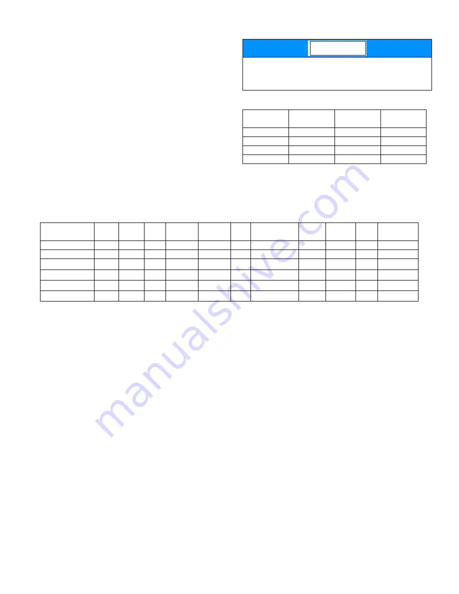
Recommended Filter Sizes
CFM
Cabinet
Size
Side
(in)
Bottom
(in)
1200
A
16 x 25
14 x 25
1200
B
16 x 25
16 x 25
1600
C
16 x 25
20 x 25
2000
C
(2) 16 x 25
20 x 25
NOTICE
Unit Clearances to Combustibles (All dimensions in inches, and all surfaces identified with the unit in an upflow configuration)
Application
Top
Front
Rear
Left
Side
Right
Side
Flue
Floor/
Bottom
Closet
Alcove
Attic
Line
Contact
Upflow
1
1
0
0
0
6
Combustible
Yes
Yes
Yes
No
Upflow B-Vent
1
1
0
0
0
1
Combustible
Yes
Yes
Yes
No
Downflow
1
1
0
0
0
6
1
1
1. Special floor base or air conditioning coil required for use on combustible floor.
Yes
Yes
Yes
No
Downflow B-Vent
1
1
0
0
0
1
1
1
Yes
Yes
Yes
No
Horizontal
1
1
0
0
0
6
Combustible
No
Yes
Yes
Yes
2
2. Line contact only permitted between lines formed by the intersection of the rear panel and side panel (top in horizontal position) of the furnace jacket and build-
ing joists, studs or framing.
Horizontal B-Vent
1
1
0
0
0
1
Combustible
No
Yes
Yes
Yes
2


