background image

5604542-UIM-B-0419

6

Johnson Controls Ducted Systems

12. Release the refrigerant charge into the system. Open the liquid line

valve first, then the vapor line valve by removing the plunger cap
and turning the valve counter-clockwise using hex head wrenches.
Valves are fully open when the valve stem is touching the cham-
fered retaining wall at the top of the valve. If the service valve is a
ball type valve, use an adjustable end wrench to turn the valve stem
one quarter turn counter-clockwise to open it. DO NOT overturn or
the valve stem may break or become damaged. See PRECAU-
TIONS DURING BRAZING SERVICE VALVE.

13. Replace service valve cap finger tight, then tighten an additional 1/

12 turn (1/2 hex flat). Cap must be replaced to prevent leaks.

14. See “System Charge” section for checking and recording system

charge. See Section VI.

SECTION IV: INDOOR EXPANSION DEVICE

THERMOSTATIC EXPANSION VALVE 

(

TXV) 

INSTALLATION

The following are the basic steps for installation. For detailed instruc-
tions, refer to the Installation Instructions accompanying the TXV kit.
Install TXV kit as follows:

1.

Relieve the holding charge by depressing Schrader core on the
suction manifold stub out.

2.

After holding charge is completely discharged, loosen and remove
the Schrader core.

3.

Place a backup wrench on distributor, loosen and remove brass
distributor nut. Retain brass nut for use on liquid line. Keep Teflon
washer in place and discard clear disk.
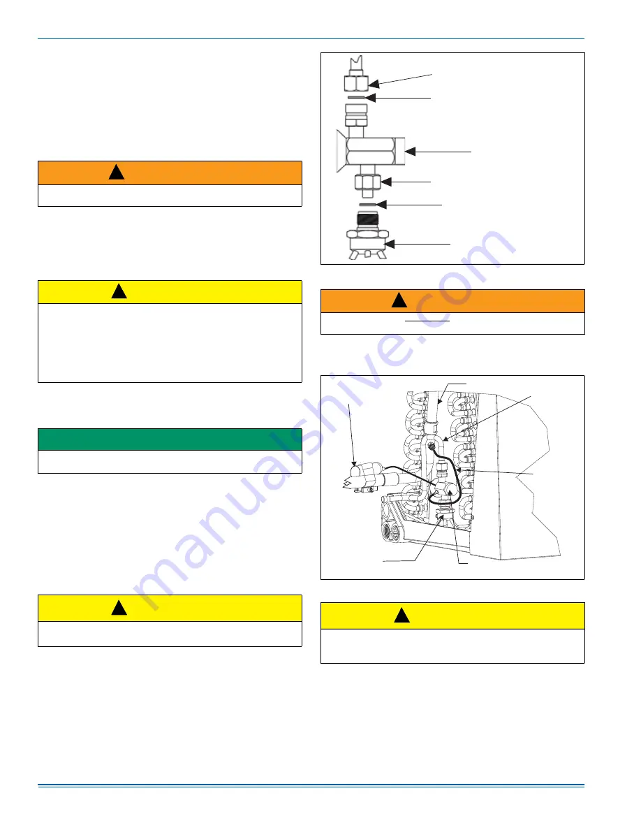
4.

Install the thermal expansion valve to the distributor assembly with
supplied fittings. Ensure Teflon washer is seated in distributor.
Hand tighten and turn an additional 1/4 turn to seal. Do not over
tighten fittings. See Figure 6.

5.

Slide the nut removed in step 3 over the supplied liquid line. Place
supplied Teflon washer from TXV kit in place on TXV, and install liq-
uid line to the top of the thermal expansion valve. Adjust assembly
so liquid line aligns with hole in access panel. Hand tighten the liq-
uid line, and apply an additional 1/4 turn to seal.

6.

Install the TXV equalizer line onto the vapor line by hand tightening

the 1/4” SAE coupling nut to the equalizer fitting, and apply an
additional 1/3 turn to seal. See Figure 7.

7.

Pass the TXV temperature sensing bulb through the suction line
split grommet in the access panel.

 WARNING

Never attempt to repair any brazed connections while the system is
under pressure. Personal injury could result.

 CAUTION

Outdoor unit model numbers ending with an “H” have a factory
installed hard start kit which is required when a TXV is installed on the
indoor unit. Outdoor unit model numbers with no “H” ending do not
require a hard start kit unless a TXV is being installed on the indoor
unit or unless local regulations dictate it. The Tabular Data Sheet
which comes with the unit specifies whether or not a hard start kit is
required. When a TXV Kit is needed, it should be ordered from
Source 1.

IMPORTANT

Refer to the Technical Guide for the unit to determine the proper TXV
kit to be used on this product.

 CAUTION

Do not over-torque. Do not use slip joint pliers. This will distort the
aluminum distributor and the brass fitting (potentially causing leaks).

!

!

!

 FIGURE 6:  

TXV Installation

 WARNING

Schrader valve core 

MUST  NOT

 be installed with TXV installation.

Poor system performance or system failure could result.

 FIGURE 7: 

TXV Bulb and Equalizer Line Installations

 CAUTION

In all cases, mount the TXV bulb after vapor line is brazed and has
had sufficient time to cool. Failure to use suction line grommet may
result in premature TXV failure.

T

X

V

 / 

D

I

STR

IB

UTOR


COUP

LING

LI

QU

I

D

 LIN

E

 /

T

X

V


COUP

LING

TE

FL

O

N W

AS

H

ER

T

X

V

TE

FL

O

N W

AS

H

ER

D

I

STR

IB

UTOR

A

0281-001

!

T

X

V

 B

U

LB

(Wrap with
insulation.)

VAPOR

 LIN

E

LI

QU

I

D

 LIN

E

TV

X

EQUA

LIZ

ER

LIN

E

T

H

ER

M

A

L

E

X

PA

N

S

I

O

N

VA

L

VE

 (

T

X

V

)

D

I

STR

IB

UTOR

B

OD

Y

A

0279-002

!

Summary of Contents for TH4 Series

Page 1: ...2 B 32 42 s Gen2 21 LIST OF TABLES Maximum Minimum Operating Limit Conditions 2 R 410A Saturation Properties 8 YHE18 Heat Charging Charts 8 YHE24 Heat Charging Charts 8 YHE30 Heat Charging Charts 9 YH...

Page 2: ...on the UPGNET web site Provide adequate structural support for the unit ADD ON REPLACEMENT RETROFIT When this unit is being used as a replacement for an R 410A unit it is required that the outdoor uni...

Page 3: ...HU EUDFH XQGHU FHQWHU RI FRPSUHVVRU 127 QVXUH DGHTXDWH ZDOO VXSSRUW 87 21 6SHFLDO FDUH PXVW EH WDNHQ WR DYRLG UHFLUFXODWLRQ RI GLVFKDUJH DLU WKURXJK RXWGRRU FRLO FIGURE 2 Alternative Installation Clea...

Page 4: ...taken not to damage the couplings or kink the tubing Use clean hard drawn copper tubing where no appreciable amount of bending around obstruction is necessary If soft copper must be used care must be...

Page 5: ...ide the grommet back into original position 6 Protect the vapor valve with a wet rag and braze the vapor line con nection to the outdoor unit The nitrogen flow should be exiting the system from the va...

Page 6: ...place on TXV and install liq uid line to the top of the thermal expansion valve Adjust assembly so liquid line aligns with hole in access panel Hand tighten the liq uid line and apply an additional 1...

Page 7: ...e for the indoor unit s static pressure vs CFM or to a curve chart CHARGING THE UNIT The factory charge in the outdoor unit includes enough charge for the unit 15 ft 4 6 m of refrigerant piping and th...

Page 8: ...80 60 70 80 60 70 80 60 70 80 60 70 80 450 Liquid Pressure PSIG 381 427 472 351 394 436 336 384 432 318 363 409 274 324 375 276 318 361 600 Liquid Pressure PSIG 345 389 434 319 355 404 308 354 400 294...

Page 9: ...58 303 348 1400 Liquid Pressure PSIG 309 351 393 292 336 381 285 332 379 272 315 357 255 299 342 246 290 335 Suction Pressure PSIG 136 109 96 80 60 52 YHE TH4 RHP14L35 CF CM CU42 AE42 AVC42 RFCX42CE C...

Page 10: ...oor Temperature F 60 70 80 60 70 80 60 70 80 60 70 80 60 70 80 60 70 80 1400 Liquid Pressure PSIG 336 384 433 312 359 406 293 344 395 279 321 364 230 290 349 248 282 316 1600 Liquid Pressure PSIG 320...

Page 11: ...cess panel FIELD CONNECTIONS POWER WIRING 1 Install the proper size weatherproof disconnect switch outdoors and within sight of the unit 2 Remove the screws at the top and sides of the corner cover Sl...

Page 12: ...ton be supplied at all times To see connection diagrams of all UPG equipment the Low Voltage System Wiring document is available online at www upgnet com in the Product Catalog Section INDOOR CUBIC F...

Page 13: ...ing table summarizes the behavior of the control when the two TEST pins are connected More detailed descriptions of the various functions are included in other sec tions of this document TABLE 11 TEST...

Page 14: ...rrangement of the refrigeration circuit within the coil The control may initiate a defrost cycle even when the coil is not completely cov ered with frost This is normal operation The control regulates...

Page 15: ...ur regardless of the liq uid line coil temperature reading The coil does not have to be cold for the unit to be forced into defrost Once the defrost cycle begins the con trol shall follow the normal d...

Page 16: ...te flash code The control will reset the soft lockout condition when any of the follow ing occur after removal of the fault condition 1 Power is cycled to the R or Y inputs of the control This will ca...

Page 17: ...OPEN REMOTE DISCONNECT SO ELECTRICAL SUPPLY TO HEAT PUMP IS SHUT OFF COMPONENTS SHOWN IN DASH LINES ARE OPTIONAL DUAL CAPACITOR SHOWN SEPARATE CAPACITORS MAY BE USED ON ACTUAL UNIT WIRING MUST CONFOR...

Page 18: ...RAL 1 2 3 4 5 LEGEND AS AMBIENT SENSOR CAP CAPACITOR CC CONTACTOR COIL CCH CRANKCASE HEATER HPS HIGH PRESS SWITCH HS HEATER SWITCH CS COIL SENSOR LPS LOW PRESS SWITCH RV REVERSING VALVE SC START CAPAC...

Page 19: ...LE PERSONAL INJURY TO PREVENT ELECTRICAL SHOCK OPEN REMOTE DISCONNECT SO ELECTRICAL SUPPLY TO HEAT PUMP IS SHUT OFF COMPONENTS SHOWN IN DASH LINES ARE OPTIONAL WIRING MUST CONFORM TO NATIONAL AND LOCA...

Page 20: ...RICAL SHOCK OPEN REMOTE DISCONNECT SO ELECTRICAL SUPPLY TO HEAT PUMP IS SHUT OFF COMPONENTS SHOWN IN DASH LINES ARE OPTIONAL WIRING MUST CONFORM TO NATIONAL AND LOCAL CODES IF ANY OF THE ORIGINAL WIRE...

Page 21: ...TOR CONNECT L2 OF CONTACTOR TO NEUTRAL 1 2 3 4 5 LEGEND AS AMBIENT SENSOR CAP CAPACITOR CC CONTACTOR COIL CCH CRANKCASE HEATER HPS HIGH PRESS SWITCH HS HEATER SWITCH CS COIL SENSOR LPS LOW PRESS SWITC...

Page 22: ...5604542 UIM B 0419 22 Johnson Controls Ducted Systems NOTES...

Page 23: ...ta Venting if applicable Electrical Line Voltage Outdoor Unit Model Outdoor Unit Serial Filter Thermostat Accessories Filter Location s Connections Per Installation Instructions and Local Codes Gas pi...

Page 24: ...ON OFF or the appropriate Value for the fields that apply to the defrost control board installed Run Time Time and Temperature board only 30 60 or 90 minutes Bonnet Sensor Present HEAT Refrigerant Ch...

Reviews: