


YORK CASSETTE (EN) 035T76015-000
CASSETTE
17
12 - SERVICE AND MAINTENANCE
The units are designed to operate for long periods of time with a minimum of maintenance. However, the following
operations must be performed regularly.
13 - TECHNICAL APPENDIX
Unit Capacity
Total cooling capacity can be determined by using
correction factors C1, C2 and C3.
Given cooling capacity = Cooling capacity at standard
rating conditions x C1 x C2 x C3.
C1 = Capacity correction factor for temperature
C2 = Capacity correction for piping length
C3 = Capacity correction for indoor unit fan speed
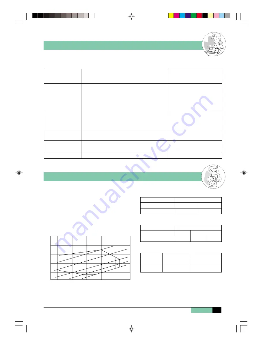
Capacity correction factor for temperature
R.C. = Standard rating condition : Indoor 27°C DB / 19.5°C WB
Outdoor 35°C DB / 24°C WB
RECOMMENDED
FREQUENCY
Every month or more often if
necessary
Every month or more often if
necessary
Each season before start up
Each season before start up.
MAINTENANCE OPERATIONS
1 - Clean with a vacuum cleaner or tap gently then wash
in warm water (40°C) with a mild detergent.
2 - Rinse and dry before replacing on unit.
3 - Never use petrol, alcohol or any oter chemical
product.
1 - Remove dust from the front panel with a soft duster
or wipe a dump cloth with a mild soap solution.
2 - Never use petrol, alcohol or any other chemical
product.
1 - Clean and check for obstructions.
1 - Check condition and remove dust from between
coil fins.
1 - No maintenance required
COMPONENT
Air filter
Unit casing
Drain pan and
evacuation piping
Indoor / Outdoor coils
Compressor
Capacity correction factor for piping length (C2)
Capacity correction factor for indoor fan speed (C3)
Operating temperature limits
Fan speed
Correction factor C3
Indoor unit
High
Medium
Low
1
0.90
0.75
Indoor unit
10
0.98
5
1.00
Piping length (m)
Correction factor C2
Maximum
Minimum
+ 19°C
(-5 with low ambient kit)
- 8°C
+ 46°C
+ 28°C
(heat pump mode)
Colling mode
Heating mode
20
10
15
20
25
30
35
25
85%
30
35
40
45
Air intake dry bulb temperature, outdoor unit (CDB)
Inlet air wet bulb temperature, indoor unit (CWB)
R.C.
Capacity correction factor C1
Operating temperature range
120%
110%
100%
90%
85%
85%
03_MKL-MKM.p65
13/6/02, 11:08 am
17


