


538605-UIM-B-1009
4
Johnson Controls Unitary Products
PRECAUTIONS DURING BRAZING SERVICE VALVE
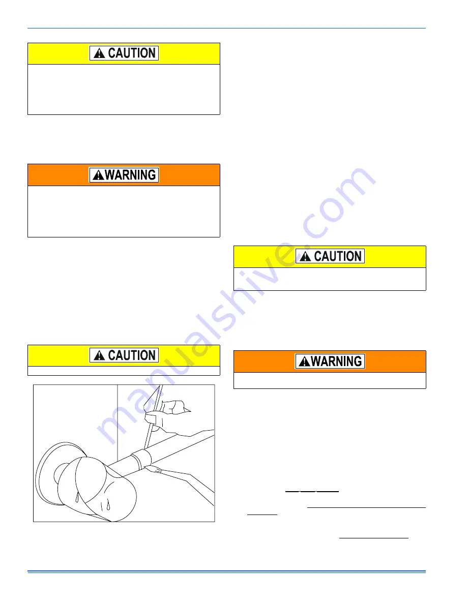
Precautions should be taken to prevent heat damage to service valve
by wrapping a wet rag around it as shown in Figure 4. Also, protect all
painted surfaces, insulation, and plastic base during brazing. After braz-
ing cool joint with wet rag.
Valve can be opened by removing the plunger cap and fully inserting a
hex wrench into the stem and backing out counter-clockwise until valve
stem just touches the chamfered retaining wall.
Connect the refrigerant lines using the following procedure:
1.
Remove the cap and Schrader core from both the liquid and vapor
service valve service ports at the outdoor unit. Connect low pres-
sure nitrogen to the liquid line service port.
2.
Braze the liquid line to the liquid valve at the outdoor unit. Be sure
to wrap the valve body with a wet rag. Allow the nitrogen to con-
tinue flowing. Refer to the Tabular Data Sheet for proper liquid line
sizing.
3.
Carefully remove the rubber plugs from the evaporator liquid and
vapor connections at the indoor coil.
4.
Braze the liquid line to the evaporator liquid connection. Nitrogen
should be flowing through the evaporator coil.
5.
Slide the grommet away from the vapor connection at the indoor
coil. Braze the vapor line to the evaporator vapor connection. After
the connection has cooled, slide the grommet back into original
position. Refer to the Tabular Data Sheet for proper vapor line siz-
ing.
6.
Protect the vapor valve with a wet rag and braze the vapor line
connection to the outdoor unit. The nitrogen flow should be exiting
the system from the vapor service port connection. After this con-
nection has cooled, remove the nitrogen source from the liquid fit-
ting service port.
7.
Replace the Schrader core in the liquid and vapor valves.
8.
Go to “SECTION IV” for TXV installation.
9.
Leak test all refrigerant piping connections including the service
port flare caps to be sure they are leak tight. DO NOT OVER-
TIGHTEN (between 40 and 60 inch - lbs. maximum).
10. Evacuate the vapor line, evaporator, and the liquid line to 500
microns or less.
NOTE:
Line set and indoor coil can be pressurized to 250 psig with dry
nitrogen and leak tested with a bubble type leak detector. Then release
the nitrogen charge.
NOTE:
Do not use the system refrigerant in the outdoor unit to purge or
leak test.
11.
Replace cap on service ports. Do not remove the flare caps from
the service ports except when necessary for servicing the system.
12. Release the refrigerant charge into the system. Open both the liq-
uid and vapor valves by removing the plunger cap and with an
allen wrench back out counter-clockwise until valve stem just
touches the chamfered retaining wall. See "PRECAUTIONS DUR-
ING BRAZING SERVICE VALVE".
13. Replace plunger cap finger tight, then tighten an additional 1/12
turn (1/2 hex flat). Cap must be replaced to prevent leaks.
See "System Charge” section for checking and recording system
charge.
SECTION IV: TXV INSTALLATIONS
For installations requiring a TXV, the following are the basic steps for
installation. For detailed instructions, refer to the Installation Instructions
accompanying the TXV kit.
Install TXV kit as follows:
1.
First, relieve the holding charge by depressing the Schrader valve
located in the end of the liquid line.
2.
After holding charge is completely discharged, loosen and remove
the liquid line fitting from the orifice distributor assembly. Note that
the fitting has
right
hand
threads
.
3.
Remove the orifice from the distributor body using a small diame-
ter wire or paper clip. Orifice is not used when the TXV assembly
is installed.
4.
After orifice is removed, install the thermal expansion valve to the
orifice distributor assembly with supplied fittings. Hand tighten and
turn an additional 1/8 turn to seal. Do not overtighten fittings.
5.
Reinstall the liquid line to the top of the thermal expansion valve.
Hand modify the liquid line to align with casing opening.
Dry nitrogen should always be supplied through the tubing while it
is being brazed, because the temperature is high enough to cause
oxidation of the copper unless an inert atmosphere is provided. The
flow of dry nitrogen should continue until the joint has cooled.
Always use a pressure regulator and safety valve to insure that only
low pressure dry nitrogen is introduced into the tubing. Only a small
flow is necessary to displace air and prevent oxidation.
This is not a backseating valve. The service access port has a
valve core. Opening or closing valve does not close service access
port.
If the valve stem is backed out past the chamfered retaining wall,
the O-ring can be damaged causing leakage or system pressure
could force the valve stem out of the valve body possibly causing
personal injury.
The evaporator is pressurized.
FIGURE 4:
Heat Protection
Do not connect manifold gauges unless trouble is suspected.
Approximately 3/4 ounce of refrigerant will be lost each time a stan-
dard manifold gauge is connected.
Never attempt to repair any brazed connections while the system is
under pressure. Personal injury could result.


