41
19.2.- Gas heating units, D4IG
Maintenance operations to be carried out by qualified per-
sonal at the beginning of the heating season:
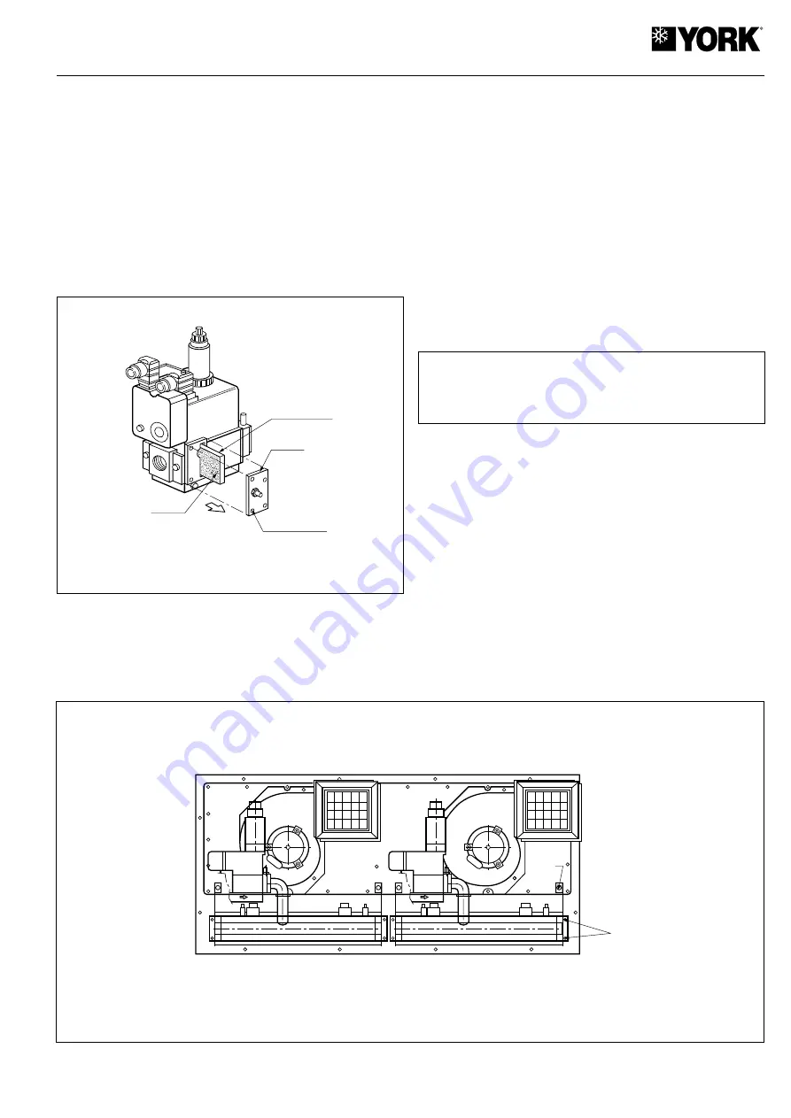
Gas valve filter
Caution:
Close the gas supply tap to the unit before access-
ing the gas valves.
Check gas filter conditions in both valves, and clean or re-
place, as required.
These are under the side cover of the valve (Fig. 2).
Place the filter into its adequate position, replace the cover
and tighten the 4 screws correctly to ensure air tightness..
Gas injectors
Visually check for partial obstruction of the calibrated holes,
and clean, if necessary (see section 19.).
Combustion air intake:
Check for any obstruction by objects or dirt.
Combustion gas discharge:
Make sure the grids are free of any obstruction by objects
or dirt.
Make sure there is no accumulation of soot on the panels,
around the smoke stacks. Should any exist, this could indicate
incomplete combustion. This should be checked by following
the indications appearing in section 18.5.
19.3.- Burner and injector inspection instruc-
tions
Burners
Visually inspect the flame of the burners (see Fig. 19). If the
flame is not correct, the burners could require cleaning. For
cleaning purposes, remove the burner assemblies as indi-
cated in section 19..
Before beginning this operation, turn the gas supply tap off, as well as
the power supply to the unit.
1. Disconnect the gas supply pipes to the unit.
2. Disconnect the gas valve cables, ignition electrodes, flame
sensors and temperature sensors.
. Disassemble the feed manifold to the gas valves by loos-
ening the 2 lock screws at the intake flange of each one,
and remove from the unit.
4. Loosen the screws that fasten both assemblies, made up
of the gas valve and the burner assembly, to the panel in
the back of this section. First remove the 4 screws from
the bottom (T1), and then the 2 from the top part (T2) (see
Fig. 24).
5. Remove the assembly from the unit (Fig. 25).
6. Now the injectors and burners are accessible for inspec-
tion and cleaning.
7. Invert this process to reinstall both assemblies.
- Fig. 24 -
- Fig. 23 -
FILTER SIDE
WITH METAL
MESH
FILTER
SCREWS (X4)
COVER
T1
T2
Summary of Contents for B4IH-360
Page 2: ......
Page 43: ...43 20 Wiring diagrams 20 1 Cool only models D4IC 360 D4IC 360G50 400 3 50 1 of 3...
Page 44: ...44 D4IC 360G50 400 3 50 2 of 3...
Page 45: ...45 D4IC 360G50 400 3 50 3 of 3...
Page 46: ...46 20 2 Cool only models D4IC 480 D4IC 480G50 400 3 50 1 of 3...
Page 47: ...47 D4IC 480G50 400 3 50 2 of 3...
Page 48: ...48 D4IC 480G50 400 3 50 3 of 3...
Page 49: ...49 20 3 Heat pump models B4IH 360 400 3 50 1 of 3...
Page 50: ...50 B4IH 360 400 3 50 2 of 3...
Page 51: ...51 B4IH 360 400 3 50 3 of 3...
Page 52: ...52 20 4 Heat pump models B4IH 480 400 3 50 1 of 3...
Page 53: ...53 B4IH 480 400 3 50 2 of 3...
Page 54: ...54 B4IH 480 400 3 50 3 of 3...
Page 55: ...55 20 5 Cool only gas heating models D4IG 360 400 3 50 1 of 4...
Page 56: ...56 D4IG 360 400 3 50 2 of 4...
Page 57: ...57 D4IG 360 400 3 50 3 of 4...
Page 58: ...58 D4IG 360 400 3 50 4 of 4...
Page 59: ...59 20 5 Cool only gas heating models D4IG 480 400 3 50 1 of 4...
Page 60: ...60 D4IG 480 400 3 50 2 of 4...
Page 61: ...61 D4IG 480 400 3 50 3 of 4...
Page 62: ...62 D4IG 480 400 3 50 4 of 4...
Page 63: ...63 Configuration of switches Data and dimensions are subject to change without prior notice...
Page 64: ...www johnsoncontrols com...


