4.4
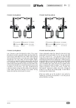
External Water System
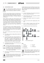
The external water hydraulic circuit must
ensure constant water flow to the evaporator
under all operating or adjustment conditions.
The plate heat exchangers fitted to YCAA-B/YCAA-H
units have multiple water passes with narrow water
channels that can be subject to premature fouling if the
design of the water system is not given adequate
consideration.
Water systems should be of the closed loop type, with
no tanks open to the atmosphere. The system should
have serviceable mesh strainers giving a filtration level
to at least 150 microns and anti-corrosion protection
using appropriate corrosion inhibitors, with
consideration to using purified water in geographic
areas where mains water has a high soluble solid
content.
York recommend that a water treatment specialist is
consulted to determine that the proposed water
composition will not affect the plate heat exchanger's
materials. Constant loss systems are not recommended
in any circumstance.
The external water system should consist of the
following:
n
A circulation pump providing sufficient output and
hydraulic head.
n
The primary system water content should be no
less than 10 litres per kW of cooling capacity. If the
total volume in primary system pipework and
evaporator is insufficient, an insulated reservoir
tank should be installed. This tank will ensure that
repetitive starts of the compressors are avoided.
n
A diaphragm-type expansion tank with safety valve
outlet which must be visible.
The tank should be sized to accommodate a
2% increase in total fluid volume in the system
(evaporator, lines, user circuits and reservoir
tank where provided). The expansion tank
does not need to be insulated, as water does
not normally circulate therein.
n
A flow switch to deactivate the unit when water is
not circulating.
The flow switch must be connected in series
with other external interlocks. The flow switch
should be installed on the pump delivery,
upstream of the unit.
A differential pressure switch is fitted as standard in the
unit. The pressure switch senses water pressure drop
across the evaporators and shuts down the unit when a
problem occurs.
In addition:
n
Install a 2” filter/strainer (150 mm mesh) on the inlet
side of the evaporator manifold.
n
Install shutoff valves on the evaporator manifold
inlet and outlet water lines.
n
Install a valved by-pass around the evaporator
manifold.
n
Install air vent valves at the highest points of the
lines.
n
Provide suitable drainage points (with plugs,
cocks, etc.) at the lowest points of the lines.
n
Insulate the pipework to prevent heat loss.
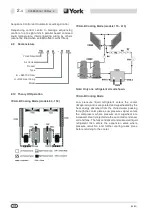
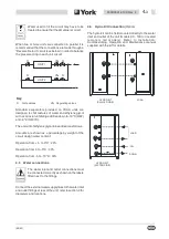
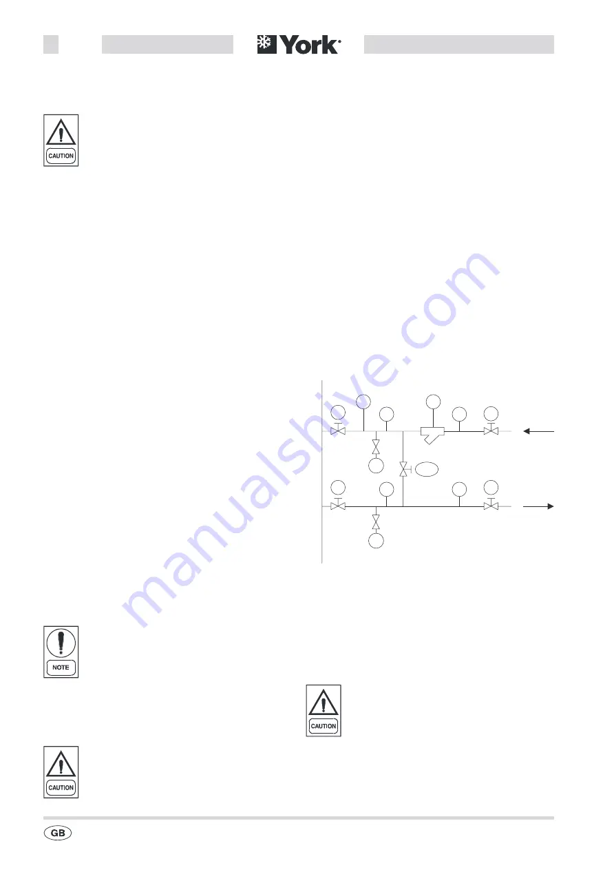
Key
I
Pressure
R
Drain tap
T
Temperature
F
Strainer
S
Gate valves
F1 Flow switch
S1 By-pass valve
Before filling the system, ensure that it is
free from foreign matter, sand, stones, rust
flakes, solder, slag or other materials which
could damage the evaporators.
It is advisable to by-pass the unit when flushing out the
lines.
(09/03)
4
-
2
035B09012-100 Rev. 4
S
S
S
E
va
po
ra
to
rM
an
ifo
ld
External Water System
T
T
I
I
S1
R
R
F1
F
S
Summary of Contents for YCAA B 120
Page 2: ......
Page 16: ...This Page Left Intentionally Blank 09 03 2 6 035B09012 100 Rev 4 ...
Page 28: ...This Page Left Intentionally Blank 09 03 4 10 035B09012 100 Rev 4 ...
Page 36: ...Page Left Intentionally Blank 09 03 6 6 035B09012 100 Rev 4 ...
Page 40: ...Page Left Intentionally Blank 09 03 7 4 035B09012 100 Rev 4 ...
Page 68: ...Notes 09 03 11 2 035B09012 100 Rev 4 ...
Page 69: ...Notes 09 03 035B09012 100 Rev 4 11 3 ...

