York International N Series Installation Manual Download Page 9

103904-UIM-B-0505

Unitary Products Group

9

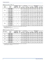
TABLE 7: Electrical Data (for Single Source Power Supply) - Copper Wire 208/230-1-60

1

N1VS Model

Heater 

Model*

Heater Amps 

240V 

Field Wiring 

Min. Circuit Ampacity

Max. O.C.P.

Amps/Type

208V

240V

208V

240V

208V

240V

B1206 

2HK*6500506B 20.8  29.1 

31.4 

30 35 

10 

2HK*6500806B 31.3  39.9 

44.4 

40 45 

2HK*6501006B 41.7  51.3 

57.5 

60 60 

2HK16501506B 62.5  74.2 

83.5 

80 90 

2HK16501806B 73.3  85.6 

97.0 

90 

100 

2HK16501906B 73.3  85.6 

97.0 

90 

100 

D1206 

2HK*6500506C 20.8  29.1 

31.4 

30 35 

10 

2HK*6500806B 31.3  39.9 

44.4 

40 45 

2HK*6501006B 41.7  51.3 

57.5 

60 60 

2HK16501506B 62.5  74.2 

83.5 

80 90 

2HK16501906C 73.3  85.6 

97.0 

90 

100 

C1606 

2HK*6500506B 20.8  30.7 

32.9 

35 35 

2HK*6500806B 31.3  41.5 

45.9 

45 50 

2HK*6501006B 41.7  52.9 

59.0 

60 60 

2HK16501506B 62.5  75.8 

85.0 

80 90 

2HK16502006B 83.3  98.0 

111.0 

100 

125 

D2006 

2HK*6500806B 31.3  43.8 

47.8 

45 50 

2HK*6501006B 41.7  55.2 

60.8 

60 70 

2HK16501506B 62.5  78.0 

86.9 

80 90 

2HK16502006B 83.3  100.3 

112.9 

110 

125 

2HK16502506B 104.2  123.1 

139.0 

125 

150 

1/0 

2HK16503006A 125.0  145.3 

165.0 

150 

175 

1/0 

2/0 

1.

Heat amps shown at 240V represents maximum heater rating.

2.

OCP = Over current protection, HACR type circuit breaker or time delay fuse.

TABLE 8: Electrical Data (for Single Source Power Supply) - Copper Wire 208/230-3-60

1

N1VS

Model

Heater 

Model*

Field Wiring

Min. Circuit Ampacity

Max. O.C.P.

Amps/Type 

Wire Size - AWG 75°C

208V

240V

208V

240V

208V

240V

B1206 

2HK06501025B 45.1  49.8 

45 

50 

2HK06501525B 45.1  49.8 

45 

50 

2HK06501825B 49.3  55.4 

50 

60 

D1206 

2HK06501025B 45.1  49.8 

45 

50 

2HK06501525B 45.1  49.8 

45 

50 

2HK06501825B 49.3  55.4 

50 

60 

C1606 

2HK06501025B 46.5  51.2 

50 

60 

2HK06501525B 46.5  51.2 

50 

60 

2HK06501825B 48.8  56.8 

50 

60 

D2006 

2HK06501025B 48.6  52.9 

50 

60 

2HK06501525B 48.6  52.9 

50 

60 

2HK06501825B 47.7  55.8 

50 

60 

NOTE: 30 KW 3 Ø not approved for single source power supply.

1.

Heat amps shown at 240V represents maximum heater rating. 

2.

OCP = Over current protection, HACR type circuit breaker or time delay fuse.

Summary of Contents for N Series

Page 1: ...ANCES 2 LOCATION 2 DUCT CONNECTIONS 4 SUSPENSION KITS 4 INDOOR UNIT PREPARATION 5 BLOWER COIL ASSEMBLY UPFLOW AND HORIZONTAL INSTALLATIONS 5 BLOWER COIL ASSEMBLY DOWNFLOW INSTALLATION 5 ELECTRIC HEATERS OPERATING CONTROLS 5 LOW VOLTAGE CONTROL CONNECTIONS 5 LINE POWER CONNECTIONS 6 BLOWER SPEED COMFORT SELECTION 6 WIRING DIAGRAMS 11 DRAIN CONNECTIONS 14 MAINTENANCE 14 COIL CLEANING 14 LUBRICATION ...

Page 2: ...ructions are required as a minimum for a safe installation GENERAL INFORMATION This Modular Air Handler provides the flexibility for installation in any upflow downflow or horizontal application These versatile models may be used with or without electric heat The variable speed ECM motors provide a selection of air volume to match any application The unit can be positioned for bottom return air in...

Page 3: ...en into consideration and provided for as follows a Refrigerant piping and connections are located in the front b Maintenance and servicing through the front or access side of unit with both sides and rear of unit having zero inch clear ance c Condensate drain lines are connected in the front clear of fil ter d Filter removal e When no electric heat is used the unit as well as all duct work and pl...

Page 4: ...charge opening sizes shown in Figure 4 Duct work should be fabricated and installed in accordance with local and or national codes This includes the standards of the National Fire Protection Association for Installation of Air Conditioning and Ventilat ing Systems NFPA No 90B SUSPENSION KITS A suspension kit is available Models 1BH0601 is designed specifically for the units contained in this instr...

Page 5: ...sly See Figure 10 Mark the unit nameplate with the appropriate heater selection on the space provided or NONE to indicate cooling only To operate these units with electric heat it is necessary to field install an electric heater kit 2HK See Electric Heater Accessory Installation instructions for proper installation procedure Prior to installing electric heat it is necessary to perform the followin...

Page 6: ...umpers on the CFM selection board as indicated in Table 2 To Set Heat Pump CFM The heat pump CFM setting is the same as the cooling CFM No addi tional CFM setting is required however you must remove the jumper at the bottom of the connector board labeled Remove for Heat Pump for heat pump operation See Figure 8 To Set Electric Heat CFM The blower speed required for the Electric Heat is different t...

Page 7: ...SINGLE SOURCE 2 5 25 KW 25 KW SHOWN 1 PHASE ELECTRIC HEAT WITH CIRCUIT BREAKER BREAKER BAR REMOVED MULTI SOURCE 15 25 KW 25 KW SHOWN TYPICAL WIRING WITHOUT ELECTRIC HEAT GND LUG POWER SUPPLY GND LUG GND LUG POWER SUPPLY GND LUG GND LUG POWER SUPPLY 1 GND LUG GND LUG POWER SUPPLY GND LUG POWER SUPPLY 2 POWER SUPPLY 3 GND LUG POWER SUPPLY GND LUG POWER WIRING 208 230 1 60 NOTE USE ONLY COPPER CONDUC...

Page 8: ...K 6500806B 0 5 1335 7 0 5 6 7 5 19 1 25 6 3 8 5 0 5 6 7 5 5 6 7 5 2HK 6501006B 7 5 10 0 25 6 34 1 3 8 5 0 7 5 10 0 7 5 10 0 2HK16501506B 11 3 15 0 38 6 51 2 3 8 5 0 7 5 10 0 11 3 15 0 2HK16502006B 15 0 20 0 51 2 68 3 3 8 5 0 7 5 10 0 15 0 20 0 2HK16502506B 18 8 25 0 64 2 85 3 3 8 5 0 11 3 15 0 18 8 25 0 2HK16503006A 22 5 30 0 76 8 102 4 7 5 10 0 15 0 20 0 22 5 30 0 1 Heat KW shown at 240V represen...

Page 9: ...55 2 60 8 60 70 6 4 2HK16501506B 62 5 78 0 86 9 80 90 4 3 2HK16502006B 83 3 100 3 112 9 110 125 2 1 2HK16502506B 104 2 123 1 139 0 125 150 1 1 0 2HK16503006A 125 0 145 3 165 0 150 175 1 0 2 0 1 Heat amps shown at 240V represents maximum heater rating 2 OCP Over current protection HACR type circuit breaker or time delay fuse TABLE 8 Electrical Data for Single Source Power Supply Copper Wire 208 230...

Page 10: ... 52 1 35 35 50 60 8 8 8 6 2HK16502006B 55 2 60 8 45 1 52 1 60 70 50 60 6 4 8 6 2HK16502506B 33 0 34 8 45 1 52 1 45 1 52 1 35 35 50 60 50 60 8 8 8 6 8 6 2HK16503006A 55 2 60 8 45 1 52 1 45 1 52 1 60 70 50 60 50 60 6 4 8 6 8 6 1 Heat amps shown at 240V represents maximum heater rating 2 OCP Over current protection HACR type circuit breaker or time delay fuse TABLE 10 Electrical Data for Multi source...

Page 11: ...y for SEER enhancement 1 Optional Dehumidification Humidistat contacts open on rise Remove Humidistat Jumper on CFM selection board Refer to CFM Selection Board Graphic Indicates convenience terminal Not functional in this application For Heat Pump Applications Remove Heat Pump Jumper on CFM selection board Refer to CFM Selection Board Graphic To change quantity of heat during HP defrost cycle Rev...

Page 12: ...t Jumper on CFM selection board Refer to CFM Selection Board Graphic Indicates convenience terminal Not functional in this application Y Terminal on Air Handler Control Board must be connected for full CFM and applications requiring 60 Second Blower Off Delay for SEER enhancement 1 Optional Dehumidification Humidistat contacts open on rise Remove Humidistat Jumper on CFM selection board Refer to C...

Page 13: ...Humidistat Jumper on CFM selection board Refer to CFM Selection Board Graphic Indicates convenience terminal Not functional in this application For Heat Pump Applications Remove Heat Pump Jumper on CFM selection board Refer to CFM Selection Board Graphic To change quantity of heat during HP defrost cycle Reverse connections at W1 W2 on Air Handler Control Board FIGURE 20 Control Wiring N1VS New UP...

Page 14: ...to be cleaned or replaced it should be washed with Calgon coilclean mix one part Coilclean to seven parts water Allow solution to remain on coil for 30 minutes before rinsing with clean water Solution should not be permitted to come in contact with painted sur faces LUBRICATION The bearings of the blower motor are permanently lubricated CONDENSATE DRAINS During the cooling season check the condens...

Page 15: ...103904 UIM B 0505 Unitary Products Group 15 NOTES ...

Page 16: ...to change without notice Printed in U S A 103904 UIM B 0505 Copyright by York International Corp 2005 All rights reserved Supersedes 103904 UIM A 1204 Unitary 5005 Norman Product York OK Group Drive 73069 NOTES ...

Reviews: